Utah-94-721002-System-Manual.pdf - 第247页
Equipment Manual lñÑçêÇ=fåëíêìãÉåíë=mä~ëã~=qÉÅÜåçäçÖó== mä~ëã~ä~Ä= f`m=NUM PKO= jÉÅÜ~åáÅ~ä=~ëëÉãÄäó= COVER PLA TE EXTRACTION COLLA R COOLI NG ELEMENT PROC ESS GAS IN LET (R OU TED FROM CHAMBER BASE) ELECTRO ST A TIC SCRE…

mä~ëã~ä~Ä=f`m=NUM lñÑçêÇ=fåëíêìãÉåíë=mä~ëã~=qÉÅÜåçäçÖó== Equipment Manual=
WARNING
THE DIELECTRIC TUBE COULD FAIL CATASTROPHICALLY BY IMPLOSION WHEN
UNDER VACUUM. IF IT IS NECESSARY TO OPEN THE RF ENCLOSURE FOR ANY
REASON, VENT THE CHAMBER, OR WEAR APPROPRIATE PERSONAL PROTECTION.
WARNING
DO NOT OPERATE THE SOURCE WITHOUT THE COVERS PROPERLY ATTACHED. PARTS
OF THE CIRCUIT OPERATE AT LETHAL VOLTAGES. RADIATION BURNS MAY OCCUR TO
NEARBY PERSONNEL.
CAUTION
Nearby electrical equipment may experience RF interference if the source is
operated without all covers and lids forming the RF enclosure properly secured.
Other components of the ICP180 include:
• A gas inlet connection, ¼ inch VCR female nut, feeding gas to distribution holes in the ICP top
lid.
• A KF25 port, intended for laser interferometry.
• A 100mm diameter extraction collar.
WARNING
IF A QUARTZ ICP TUBE IS FITTED, ULTRA-VIOLET LIGHT FROM THE PLASMA CAN
FORM OZONE IN THE AIR INSIDE THE RF ENCLOSURE. EXTRACTION SHOULD BE
FITTED TO THIS PORT; EXTRACTION SHOULD BE FITTED IF THE GASES USED POSE A
HAZARD TO PERSONNEL SHOULD THE ICP TUBE BREAK.
• An electrostatic screen. This minimises capacitive coupling between the RF induction coil and the
plasma, which in turn reduces ion bombardment of the tube wall. It also eliminates cross-
coupling between the ICP RF supply and any other RF generator on the same chamber, making
phase-locking unnecessary. The electrostatic screen can be omitted if the ICP 180 is the only
plasma source on the chamber.
• A pressure relief port. Should the system become pressurised, this will automatically open to
prevent dangerous pressurisation of the ICP tube.
ICP 180 Source
Issue 4: January 06 Page 6 of 26 Printed: 18-Jan-06, 8:44
Equipment Manual lñÑçêÇ=fåëíêìãÉåíë=mä~ëã~=qÉÅÜåçäçÖó== mä~ëã~ä~Ä=f`m=NUM
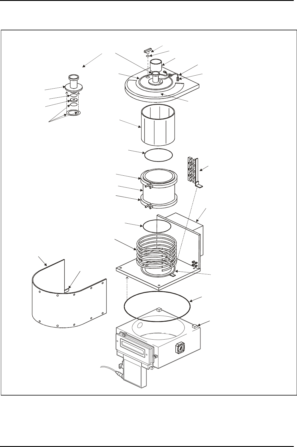
PKO= jÉÅÜ~åáÅ~ä=~ëëÉãÄäó=
COVER PLATE
EXTRACTION
COLLAR
COOLING
ELEMENT
PROCESS GAS
INLET (ROUTED
FROM CHAMBER
BASE)
ELECTROSTATIC
SCREEN
(OPTION)
INSULATING
TUBE
COOLING
COLLAR
COOLING
COLLAR
O-RING SEAL
TO COVER PLATE
O-RING SEAL
TO CHAMBER LID
AUTOMATCH
UNIT
O-RING SEAL
CHAMBER LID
TO CHAMBER
HINGE
BLOCK
COVER
RF COIL
(WATER COOLED)
CHAMBER LID
COOLING CIRCUIT
COIL CLAMPING
ASSEMBLY
AIR INLET
GRID
ENDPOINT
DETECTOR
PORT
DETAILS
PRESSURE
RELIEF VALVE
NW25KF FLANGE
GASKET
SAPPHIRE
WINDOW
O RING SEAL
NW16 CENTRING RING
COVER INTERLOCK
ACTUATOR
Fig 2: ICP 180 Exploded view
ICP 180 Source
Printed: 18-Jan-06, 8:44 Page 7 of 26 Issue 3 : December 00

mä~ëã~ä~Ä=f`m=NUM lñÑçêÇ=fåëíêìãÉåíë=mä~ëã~=qÉÅÜåçäçÖó== Equipment Manual=
The mä~ëã~ä~Ä f`m=NUM is an assembly which can be fitted to a mä~ëã~ä~Ä
=
póëíÉã=NMM=chamber in place of
the standard chamber lid. The assembly comprises a chamber lid on which is mounted the ICP discharge
chamber, an automatch unit and a shielding cover.
The chamber lid is secured to the process chamber by hinges which allow it to be tilted for process
chamber maintenance. The lid is water cooled by a circular cooling element. Vacuum sealing between the
lid and the process chamber is provided by an O-ring. A mounting plate attached to the lid supports the
automatch unit.
The discharge chamber comprises an insulated tube sealed at its top and bottom by O-rings. The insulated
tube is cooled at its top and bottom by cooling collars. An electrostatic shield surrounds the insulated
tube. A water-cooled RF induction coil, supported by two clamping assemblies, is located outside of the
insulated tube and electrostatic shield.
The top of the discharge chamber is a cover plate which incorporates an extraction cover, endpoint
detector port, process gas inlet, pressure relief valve and a circular cooling element. Air is drawn into the
space outside of the discharge chamber through a cooling grid.
The ICP 180 cover incorporates an interlock actuator (see Fig 2) which, when the cover is fitted, actuates a
micro-switch located under the AMU. When the micro-switch is actuated, the contactor which supplies the
source's RF Generator, is enabled. When the cover is not fitted, the RF Generator's supply is disabled.
PKP= pçìêÅÉ=ëéÉÅáÑáÅ~íáçå=
Description:
Inductively coupled plasma source for use with the mä~ëã~ä~Ä
=
póëíÉã=NMM=.
RF: Minimum generator capacity 1200W
Maximum RF power handling 3000W
Frequency: 13.56MHz.
Ion current density:
>1mA/cm
-2
at normal substrate position in the mä~ëã~ä~Ä
=
póëíÉã=
NMM, using Argon at 1 Pa.
Pressure range: 0.5Pa to10Pa (3 to 70 mTorr). (Argon) Operation to 1mTorr is
possible using >2KW RF.
Vacuum: All joints < 5 x 10
-8
mbar litre/sec leak rate on Helium leak test.
ICP 180 Source
Issue 4: January 06 Page 8 of 26 Printed: 18-Jan-06, 8:44