Utah-94-721002-System-Manual.pdf - 第283页
System Manual lñÑçêÇ=fåëí êìãÉåíë=mä~ëã~=qÉÅÜåçäçÖó== ^ää=lfmq=póëíÉãë SKNKO= aêáîÉ=ãçíçê=ëÜ~Ñí=íç=Å~é~Åáíçê=ëéáåÇäÉ=~äáÖåãÉåí= Refer to Symptom (F) in the Fault diagno sis chart (s ub-section 6.1, page 15). If the coupl…
^ää=lfmq=póëíÉãë lñÑçêÇ=fåëíêìãÉåíë=mä~ëã~=qÉÅÜåçäçÖó== System Manual
SYMPTOM POSSIBLE CAUSES ACTION
(E) C1 or C2 oscillate
close to match
1. Amplifier gain too high
2. C1 or C2 spindle thread
dirty.
See sub-section 6.1.1 (page 16).
Remove capacitor, clean and re-lubricate
capacitor’s spindle thread and bearing. Re-
align; see sub-section 6.1.2 (page 17).
(F) Drive motor shafts
rotate but capacitor
spindles do not.
Coupling between the motor
shafts and capacitor spindles
has become disengaged or
loose.
See sub-section 6.1.2 (page 17).
(G) End stops don’t
work, motor drives
through.
Park potentiometers have
broken
Check park potentiometers behind AMU
control panel and replace if necessary.
(H) Error signal pots
don’t adjust the
error signal or both
adjust one signal
only.
Links placed incorrectly Check links LK6, 7, 10 & 107 to ensure they are
in the correct position. If link is open end type,
ensure that metal insert is still present.
Hints and Tips
• Do not remove anything from the Motor Control board without removing the
power (JP2) first.
• When in ‘Auto’ mode RV1 and RV2 found on the side of the AMU casing can be used
to make fine adjustments to the match position.
SKNKN= ^ãéäáÑáÉê=Ö~áå=~ÇàìëíãÉåí=
Refer to Symptom (E) in the Fault diagnosis chart (see sub-section 6.1, page 15).
When adjusting the amplifier gain, initially adjust the associated variable resistor (RV101 for
C1 or RV1 for C2; see for locations). These variable resistors provide a ‘fine’ adjustment. If
required, a coarse adjustment is available by using links LK102 and LK2 as shown in Fig 7.
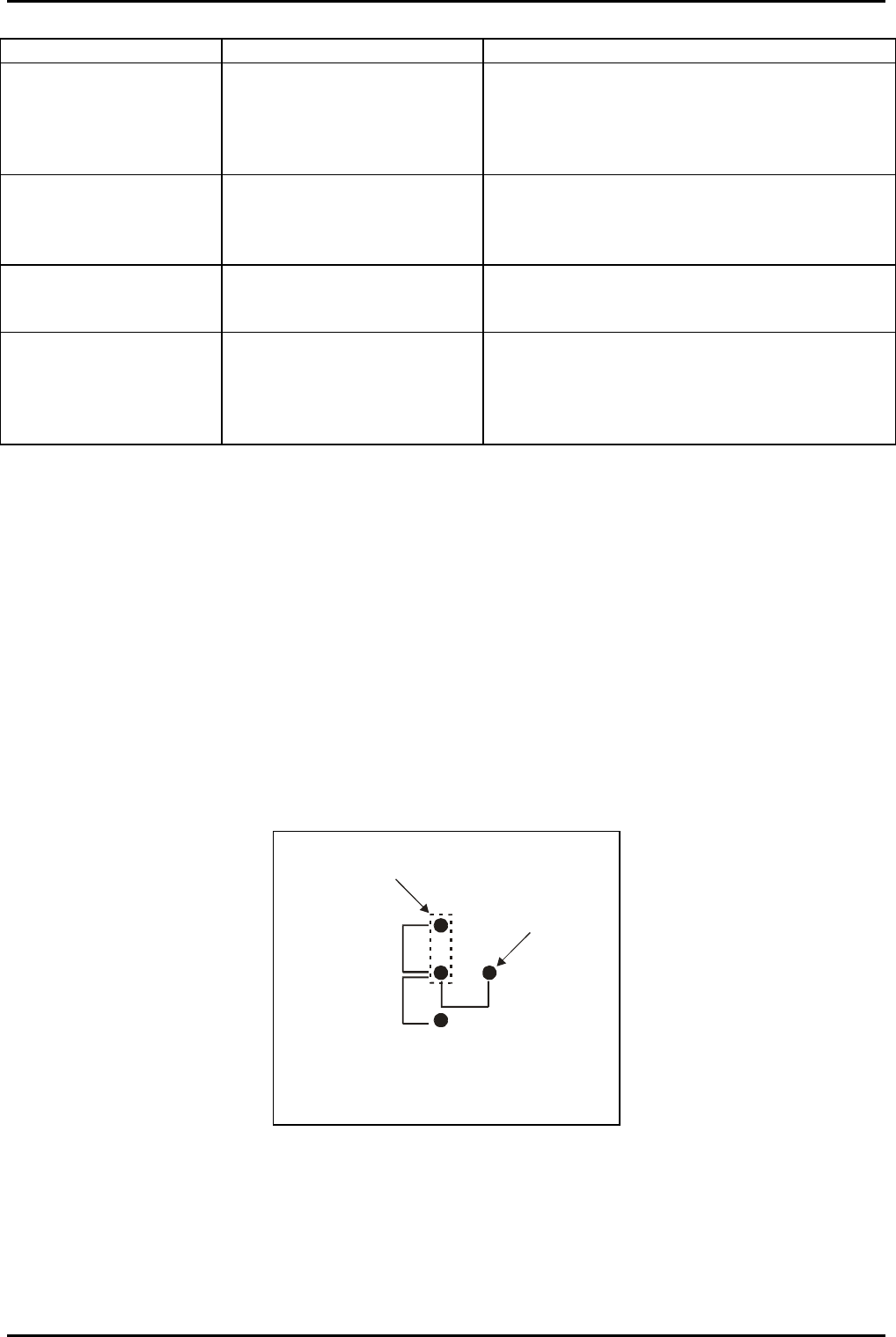
A
B
C
Pin on
PCB
Link shown in
position A
Position A = Lowest amplifier gain
Position B = Medium amplifier gain
Position C = Highest amplifier gain
Fig 7: LK102 and LK2 settings
OIPT Automatch Unit
Issue 6: February 05 Page 16 of 20 Printed: 5-Jan-06, 8:03

System Manual lñÑçêÇ=fåëíêìãÉåíë=mä~ëã~=qÉÅÜåçäçÖó== ^ää=lfmq=póëíÉãë
SKNKO= aêáîÉ=ãçíçê=ëÜ~Ñí=íç=Å~é~Åáíçê=ëéáåÇäÉ=~äáÖåãÉåí=
Refer to Symptom (F) in the Fault diagnosis chart (sub-section 6.1, page 15).
If the coupling between the motor shafts and capacitor spindles, has become disengaged or
loose, use the following procedure to align the shafts/spindles to their correct relative
positions.
1) Tighten the shaft and spindle grub screws.
2) Loosen the two bolts securing the motor/gear assembly to the AMU casing.
3) Carefully slide the motor/gear assembly away from the fan housing to disengage the
gear wheels from the capacitor.
4) Align the gear wheels to the capacitor depending on the AMU version as follows:
a) Air spaced capacitor
AMUs
(i) At the AMU control panel, set the relevant MANUAL/AUTO
switch to MANUAL.
(ii) Set the relevant MAX/MIN switch to MAX.
(iii) Fully mesh the capacitor vanes.
b) Vacuum capacitor
AMUs for RIE/PECVD
applications
(i) At the AMU control panel, set the relevant
MANUAL/AUTO switch to MANUAL.
(ii) Set the relevant MAX/MIN switch to MAX.
(iii) Set the relevant capacitor to maximum by rotating its
shaft anti-clockwise until the shaft becomes loose and
starts to unscrew from the capacitor body, then rotate
the shaft one turn clockwise.
c) Vacuum capacitor
AMUs for the ICP 180
application
For C1, use the procedure in b) above.
For C2, use the following steps:
(i) At the AMU control panel, set the C2 MANUAL/AUTO
switch to MANUAL.
(ii) Set the C2 MAX/MIN switch to MIN.
(iii) Set C2 to minimum by rotating its shaft clockwise until
the physical end stop is reached, and then rotate the
shaft one turn anti-clockwise.
d) Vacuum capacitor
AMUs for RF ion
source applications
For C1 and C2 alignment in this AMU, use the procedure for C2
in c) above.
5) On completion of capacitor alignment in Step 4), re-engage the motor/gear assembly
to the capacitor and tighten the securing bolts.
6) Check capacitor travel.
OIPT Automatch Unit
Printed: 5-Jan-06, 8:03 Page 17 of 20 Issue 6: February 05

^ää=lfmq=póëíÉãë lñÑçêÇ=fåëíêìãÉåíë=mä~ëã~=qÉÅÜåçäçÖó== System Manual
SKO= iáåâ=pÉííáåÖë=
Incorrect link settings can cause the AMU to malfunction. The factory default settings are
given in the following table:
Link
Air
spaced
Capacitor
Low Power
Vacuum
Capacitor
High Power
Vacuum
Capacitor
Notes
LK1
A A A Setting A enables park position.
Setting B disables park.
LK2
B A B Coarse gain setting for C2 (‘A’ – low, ‘B’ –
medium, ‘c’ - high)
LK3
A A A Setting ‘B’ simulates RF on signal (for
testing only).
LK4
B A A Incremental Gain Signal. LK4 in position
‘A’ enables extra gain when in position
control. This is used when driving a
vacuum capacitor.
LK5
A A A Panel/PLC Controller. Position B for AMU
controlled by PLC
LK6
A A B Changes the biasing on the input
amplifier for C2 motor
LK7
B B A Changes the biasing on the input
amplifier for C2 motor
LK101
A A A Setting ‘A’ enables park position.
Setting ‘B’ disables park.
LK102
B A B Coarse gain setting for C1 (‘A’ – low, ‘B’ –
medium, ‘C’ - high)
LK104
B A A Incremental Gain Signal. LK104 in position
‘A’ enables extra gain when in position
control. This is used when driving a
vacuum capacitor.
LK105
A A A Panel/PLC Controller. Position ‘B’ for AMU
controlled by PLC
LK106
A A B Changes the biasing on the input
amplifier for C1 motor
LK107
A A B Changes the biasing on the input
amplifier for C1 motor
OIPT Automatch Unit
Issue 6: February 05 Page 18 of 20 Printed: 5-Jan-06, 8:03