Utah-94-721002-System-Manual.pdf - 第30页
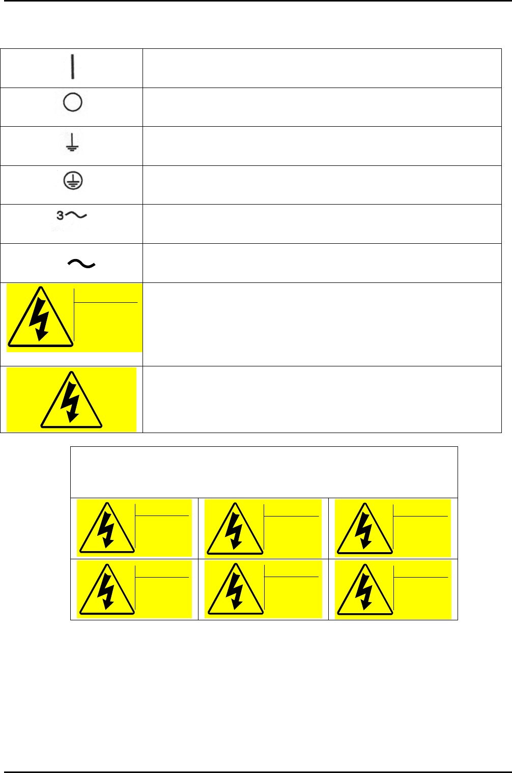
mä~ëã~ä~Ä and fçåÑ~Ä lñÑçêÇ=fåëíêìãÉåíë=mä~ëã~=qÉÅÜåçäçÖó= Health and Safety …Continued On (Supply) IEC 417, No.5007 Off (Supply) IEC 417, No.5008 Earth (ground) IEC 417, No.5017 Protective earth (ground) IEC 417, No.501…
Health and Safety lñÑçêÇ=fåëíêìãÉåíë=mä~ëã~=qÉÅÜåçäçÖó= mä~ëã~ä~Ä and fçåÑ~Ä
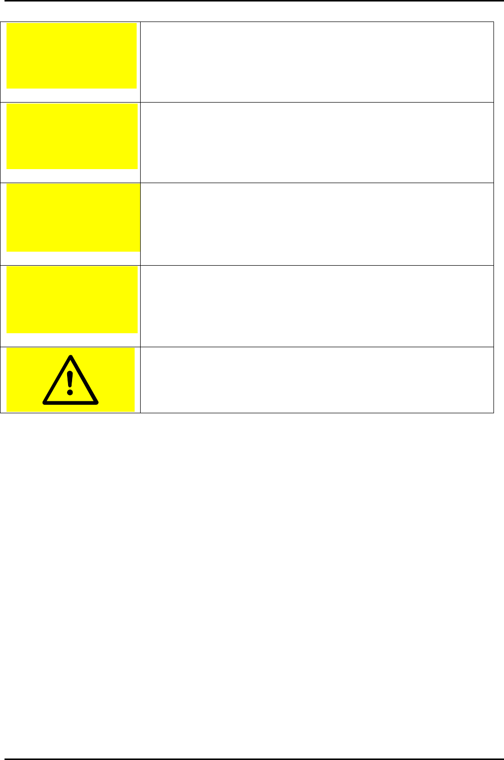
System vent gas: Nitrogen
Max inlet pressure : 5 Bar
WARNING
Warns of gas type and maximum pressure, connected to the system.
Gas type: Air (compressed)
Max inlet pressure : 9 Bar
WARNING
Warns of gas type and maximum pressure, connected to the system.
System process gas :
Max inlet pressure : 5 Bar
WARNING
Warns of gas type and maximum pressure, connected to the system.
Fluid type: Water (cooling)
Max inlet pressure : 4.2 Bar
WARNING
Warns of fluid type and maximum pressure, connected to the system
Caution, refer to accompanying documents. ISO 3864, No. B.3.1
Continued…
Health and Safety
Printed:29 May 2005, 06:31 Page 1-17 of 18 Issue 11: August 2004
mä~ëã~ä~Ä and fçåÑ~Ä lñÑçêÇ=fåëíêìãÉåíë=mä~ëã~=qÉÅÜåçäçÖó= Health and Safety
…Continued
On (Supply) IEC 417, No.5007
Off (Supply) IEC 417, No.5008
Earth (ground) IEC 417, No.5017
Protective earth (ground) IEC 417, No.5019
Three phase alternating Current IEC 617-2 No. 020206
3N
Three phase alternating Current with Neutral wire.
W
ARNING
HAZARDOUS
VOLTAGE
Disconnect electrical
supply before
removing cover
Warns of any voltage between 208V and 240V underneath the cover.
When used on its own, this label warns of any voltage between 208V
and 240V.
The labels below indicate the presence of high voltages within the labelled
equipment. There is a danger of electric shock or burns from touching
components within the labelled equipment.
DANGER
HAZARDOUS
VOLTAGE
415 Volts
50/60 hz
3 Phase
DANGER
HAZARDOUS
VOLTAGE
380 Volts
50/60 hz
3 Phase
DANGER
HAZARDOUS
VOLTAGE
208 Volts
50/60 hz
3 Phase
DANGER
HAZARDOUS
VOLTAGE
240 Volts
50/60 hz
DANGER
HAZARDOUS
VOLTAGE
220 Volts
50/60 hz
DANGER
HAZARDOUS
VOLTAGE
115 Volts
50/60 hz
Health and Safety
Issue 11: August 2004 Page 1-18 of 18 Printed:29 May 2005, 06:31

System Manual lñÑçêÇ=fåëíêìãÉåíë=mä~ëã~=qÉÅÜåçäçÖó== mä~ëã~ä~Ä=póëíÉã=NMM
OK= pÉêîáÅÉë=Ef`m=NUM=C=~ìíçã~íáÅ=äç~Ç=äçÅâF=
2.
Services (ICP 180 & automatic load lock) ...................................................................................2-1
2.1 General....................................................................................................................................................2-2
2.2 Services requirements ............................................................................................................................2-3
2.3 Distribution and use of Nitrogen vent and turbo purge gas..............................................................2-3
2.4 Services diagrams ...................................................................................................................................2-4
Fig 2.1: System 100 (ICP 180/380) services flow diagram..................................................................................2-5
Fig 2.2: System 100 pneumatic circuit diagram.................................................................................................2-6
Services (ICP 180 and Automatic Load Lock)
Printed 25 May 2005 10:12 Page 2-1 of 6 Issue 2: February 02