Utah-94-721002-System-Manual.pdf - 第35页
System Manual lñÑçêÇ=fåëíêìãÉåíë=mä~ëã~=qÉÅÜåçäçÖó== mä~ëã~ä~Ä= póëíÉã=NMM Fig 2.1: System 100 (ICP 180/380) servi ces flow diagram Services (ICP 180 and Automatic Load Lock) Printed 25 May 2005 10:12 Page 2-5 of 6 Issue…

mä~ëã~ä~Ä=póëíÉã=NMM lñÑçêÇ=fåëíêìãÉåíë=mä~ëã~=qÉÅÜåçäçÖó== System Manual
software to display a blue system alert followed after three minutes by a red system alert and
subsequent system shut down to prevent damage to the turbo pump. For details of system
alerts, see Section 5 (Operating Instructions.).
The turbo purge valve is pneumatically controlled by the system software.
mêçÅÉëë=ÅÜ~ãÄÉê=îÉåí=äáåÉ=
The process chamber vent line supplies nitrogen to the process chamber during the venting
sequence via a restrictor and chamber vent valve. The chamber vent valve is pneumatically
controlled by the system software.
cçêÉäáåÉ=îÉåí=äáåÉ=
The foreline vent line supplies nitrogen to the foreline during the venting sequence to
prevent backstreaming of vapour from the rotary vane pump. Nitrogen is fed from the
regulator to the foreline via a restrictor and the foreline vent valve. The foreline vent valve is
opened for a period when the primary vacuum pump is turned off.
^ìíçã~íáÅ=äç~Ç=äçÅâ=îÉåí=äáåÉ=
The automatic load lock vent line supplies nitrogen to the automatic load lock during the
venting sequence via a restrictor and chamber vent valve. The chamber vent valve is
pneumatically controlled by the system software.
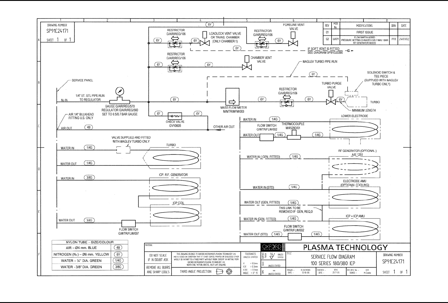
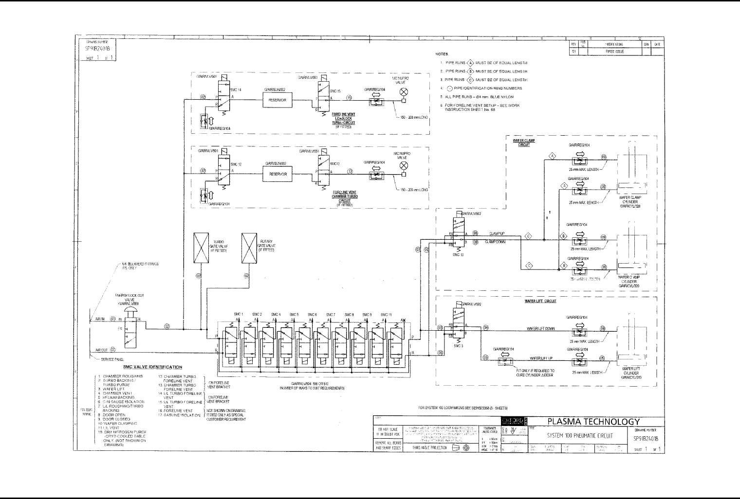
OKQ= pÉêîáÅÉë=Çá~Öê~ãë=
The services flow and pneumatic circuit are shown in the following diagrams. Note that these
are typical schematics; actual components fitted depend on the options supplied.
Services (ICP 180 and Automatic Load Lock)
Issue 2: February 02 Page 2-4 of 6 Printed 25 May 2005 10:12
System Manual lñÑçêÇ=fåëíêìãÉåíë=mä~ëã~=qÉÅÜåçäçÖó== mä~ëã~ä~Ä=póëíÉã=NMM
Fig 2.1: System 100 (ICP 180/380) services flow diagram
Services (ICP 180 and Automatic Load Lock)
Printed 25 May 2005 10:12 Page 2-5 of 6 Issue 2: February 02
mä~ëã~ä~Ä=póëíÉã=NMM lñÑçêÇ=fåëíêìãÉåíë=mä~ëã~=qÉÅÜåçäçÖó== = System Manual
Fig 2.2: System 100 pneumatic circuit diagram
Services (ICP 180 and Automatic Load Lock)
Issue 2: February 02 Page 2-6 of 6 Printed 25 May 2005 10:12