Utah-94-721002-System-Manual.pdf - 第36页
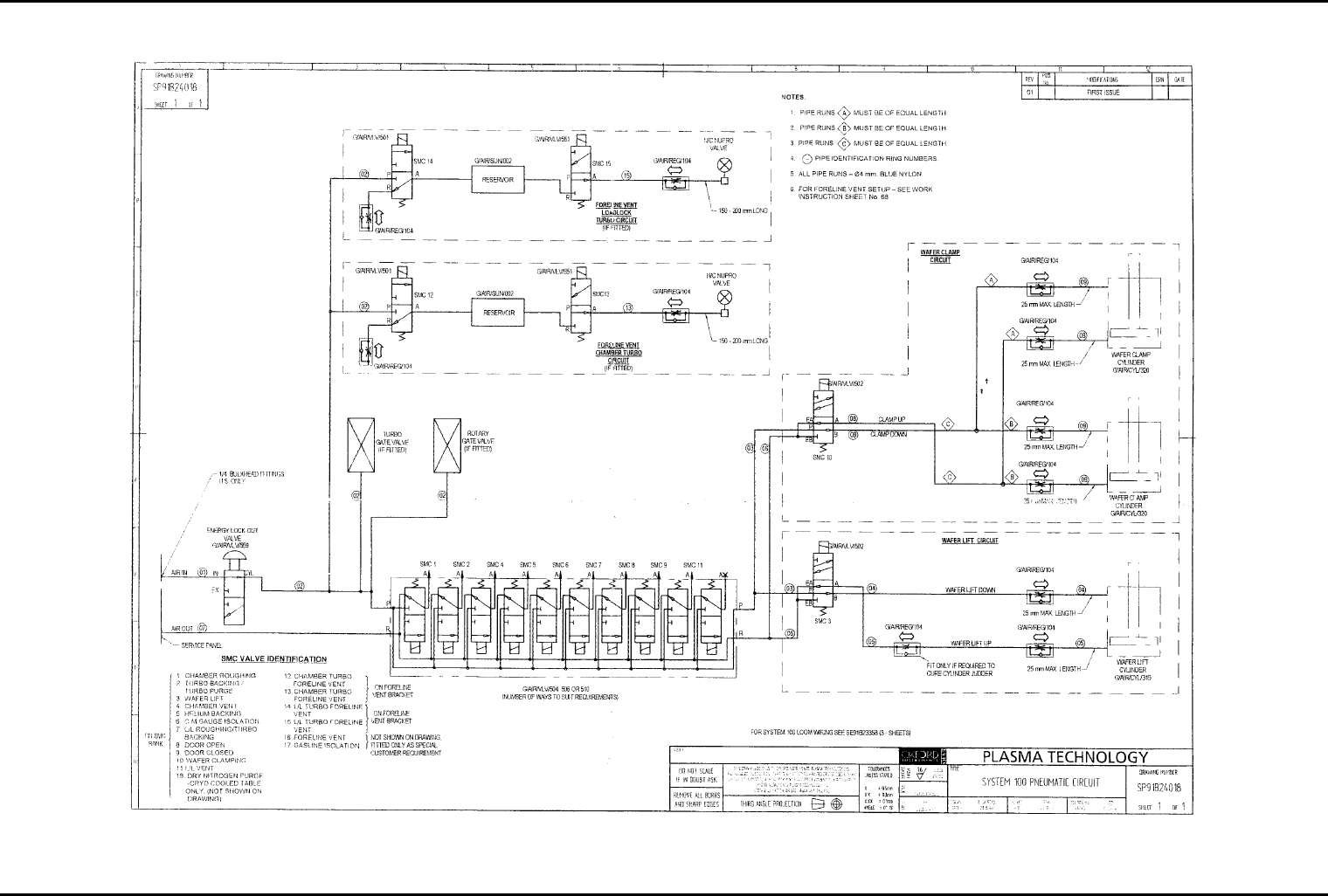
mä~ëã~ä~Ä= póëíÉã=NMM lñÑçêÇ=fåëíêìãÉåíë=mä~ëã~=qÉÅÜåçäçÖó== = System Manual Fig 2.2: System 100 pneumatic ci rcuit diagram Services (ICP 180 and Automatic Load Lock) Issue 2: February 02 Page 2-6 of 6 Printed 25 May 200…
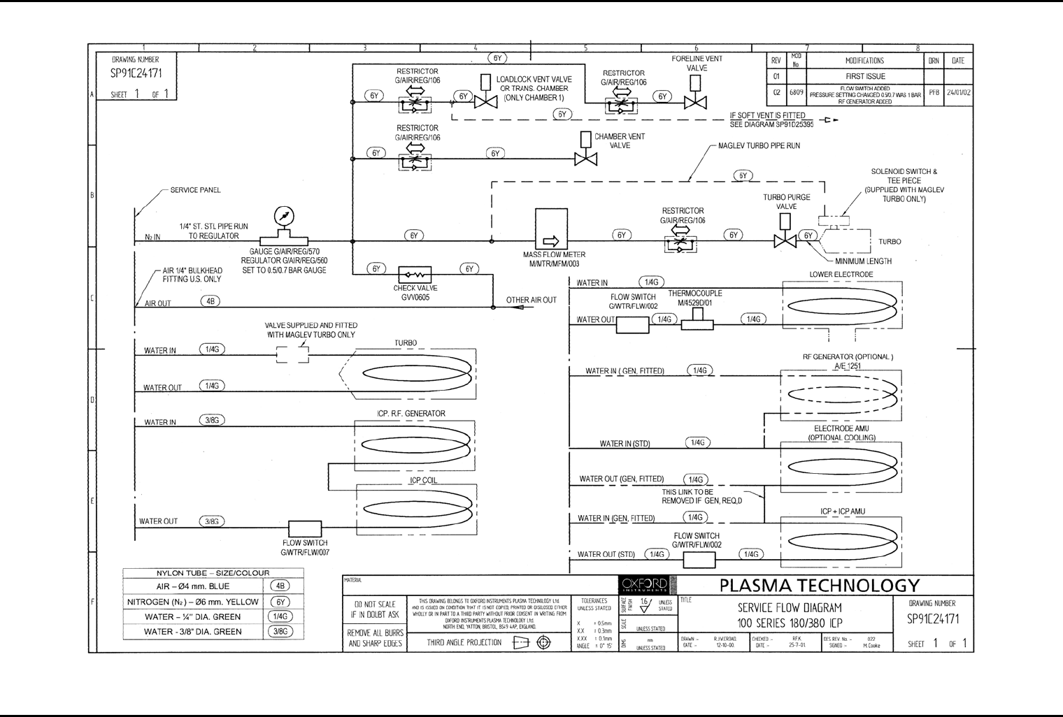
System Manual lñÑçêÇ=fåëíêìãÉåíë=mä~ëã~=qÉÅÜåçäçÖó== mä~ëã~ä~Ä=póëíÉã=NMM
Fig 2.1: System 100 (ICP 180/380) services flow diagram
Services (ICP 180 and Automatic Load Lock)
Printed 25 May 2005 10:12 Page 2-5 of 6 Issue 2: February 02
mä~ëã~ä~Ä=póëíÉã=NMM lñÑçêÇ=fåëíêìãÉåíë=mä~ëã~=qÉÅÜåçäçÖó== = System Manual
Fig 2.2: System 100 pneumatic circuit diagram
Services (ICP 180 and Automatic Load Lock)
Issue 2: February 02 Page 2-6 of 6 Printed 25 May 2005 10:12

System Manual lñÑçêÇ=fåëíêìãÉåíë=mä~ëã~=qÉÅÜåçäçÖó== mä~ëã~ä~Ä póëíÉã=NMM
PK= aÉëÅêáéíáçå=
3. Description....................................................................................................................................3-1
3.1 Introduction...........................................................................................................................3-2
3.2 PC 2000 Hardware and software with licence.....................................................................3-2
3.2.1 Hardware......................................................................................................................................3-2
3.2.2 PC 2000 software and single-user licence...................................................................................3-2
3.3 94-100-0-RIE RIE base unit.....................................................................................................3-2
3.3.1 Frame ............................................................................................................................................3-3
3.3.2 Power box assembly.....................................................................................................................3-3
3.3.3 System controller..........................................................................................................................3-3
3.3.4 Interlocks.......................................................................................................................................3-5
3.3.5 Services..........................................................................................................................................3-6
3.4 94-100-3-41C ICP 180 chamber kit with gate valve.............................................................3-7
3.4.1 94-100-3-00/21P Process chamber electrical heating kit............................................................3-8
3.4.2 94-100-3-00/05 200mm Pumpdown pipe heater kit ..................................................................3-8
3.5 94-100-5-12A Cryo / heated –150/400C helium-assisted lower electrode..........................3-9
3.6 94-100-6-500/200 500W RF generator / OIPT AMU kit........................................................3-12
3.7 94-100-6-56 ICP 180 Inductively Coupled Plasma Source..................................................3-12
3.8 Vacuum system....................................................................................................................3-12
3.9 Gas handling system...........................................................................................................3-14
3.9.1 94-81-9-51/8 Gas pod (PLC version)...........................................................................................3-14
3.9.2 94-81-9-11 Standard non-toxic gas line....................................................................................3-16
3.9.3 94-81-9-21 Standard toxic gas line............................................................................................3-17
3.9.4 94-81-9-00/4 Gas line interlock kit ............................................................................................3-17
3.10 94-100-10-05C Single wafer automatic load lock ............................................................3-18
3.10.1 Wafer transfer mechanism operating principle.......................................................................3-19
3.10.2 Functional Description...............................................................................................................3-20
3.10.3 Wafer support (end effector)....................................................................................................3-22
Fig 3.1: Typical control system............................................................................................................................3-4
Fig 3.2: 94-100-3-41C process chamber..............................................................................................................3-7
Fig 3.3: 94-100-5-12A Cryo / heated -150 / 400C He lower electrode............................................................3-11
Fig 3.4: UC Davis 94-721001 vacuum system ...................................................................................................3-13
Fig 3.5: 94-81-9-51 Gas pod .............................................................................................................................3-15
Fig 3.6: 94-81-9-11 Standard non-toxic gas lines.............................................................................................3-16
Fig 3.7: 94-81-9-21 Standard toxic gas line......................................................................................................3-17
Fig 3.8: Single wafer automatic load lock.......................................................................................................3-18
Fig 3.9: Simplified wafer transport mechanism operation.............................................................................3-19
Fig 3.10: Automatic load lock, side view .........................................................................................................3-20
Fig 3.11: Automatic load lock wafer transport mechanism ...........................................................................3-21
Table 3.1: Consequences of open circuit interlocks..........................................................................................3-6
Description
Printed: 22-Mar-06, 7:29 Page 3-1 of 22 UC Davis 94-721001 Issue 1: March 06