Utah-94-721002-System-Manual.pdf - 第9页
Page 1 of 4 SYSTEM READINESS FORM This form is provided in orde r for us to record the level of work that you have conducted, to support the installation of your new Oxford Instruments system. The system should be insta …

QCF 61 Issue 7
Sheet 2/2
Oxford Instruments Plasma Technology
North End, Yatton
Bristol, BS49 4AP
England.
Telephone : +44 (0) 1934 837000
Fax: +44 (0) 1934 837001
E mail: plasma.technology@oxinst.co.uk
`boqfcf`^qb=lc=^``bmq^k`b=
Please ask our representative for a copy of our Customer feedback form, in order that you may record your
opinions of the service given by Oxford Plasma Technology Ltd.
Brief description of the system:
Pre-acceptance form completed at OIPT ? Yes / No
Customer:
Project number:
Equipment serial number/s:
Witnessed by: Oxford Instuments Plasma Technology representative
Signature: Date: / / 0
Accepted by: Representative of the end user.
Signature: Date: / / 0
The equipment supplied has been examined and tested as an assembled system in my
presence, and has given satisfactory results where shown. (Tick as appropriate)
Operational Process
I am satisfied with the results that this system has produced and I accept that the technical
specifications have been achieved.
Comments:-
OIPT circulation:
Service Manager
Design Manager
Page 1 of 4
SYSTEM READINESS FORM
This form is provided in order for us to record the level of work that you have conducted, to support the installation of your new Oxford
Instruments system. The system should be installed, within the parameters listed below and the form returned to your supporting Oxford
Instruments office. Returning this form signifies that you have completed the installation of the system, in accordance with the Services
and Specifications data sheet and that the installation conforms with all of the requirements listed within. Should you not have a copy of
the afore-mentioned “Services & Specifications” data sheet, you should contact your supporting Oxford Instruments office immediately
and obtain a copy.
Should this form be received, an engineer dispatched to start commissioning and any of the facilities requirements not be
met, Oxford Instruments reserves the right to terminate that commissioning visit and charge the customer for a return
visit, once the facilities have been fully completed.
Company Name :
Company Contact
Name:
System Serial
Number :
System Type:
Please tick appropriate box YES NO Detail
1. Has the system been sited ? Attach site plan if available.
2. Has the system been installed in a clean room ?
3. Are there any special requirements for gaining access into the clean
room ? ie. clearance, training, citizenship etc.. If so please list below.
4. Have pumps been sited and the cables between each pump and
system power box been connected?
5. Has the gas pod been sited, connected to the system and connected
in to the appropriate gas delivery and exhaust extraction systems, in
accordance with local safety regulations?
6. If the system has a heater chiller, has this been sited, connected to
the lower electrode cooling circuit and filled with Hexid A40?
QCF 89 Issue 6
QCF 89 Issue 6
Page 2 of 4
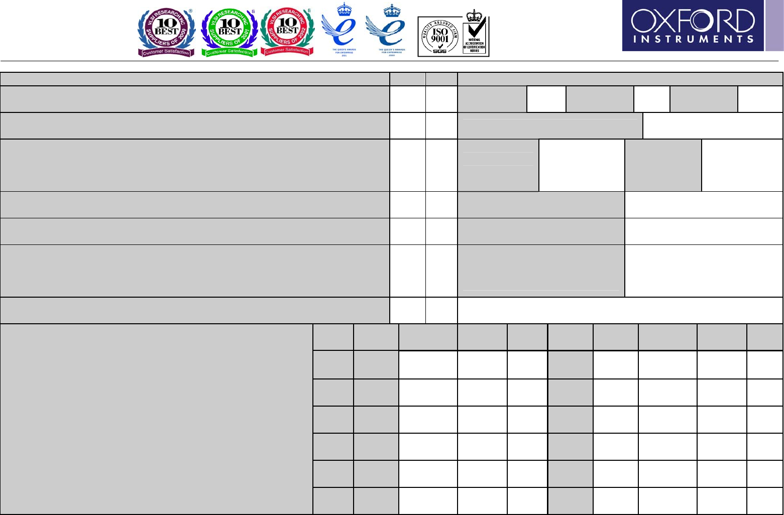
Please tick appropriate box YES NO Detail
7. Has AC power been connected to the system? Measure the voltages
between each phase and neutral.
Phase 1 to
Neutral
Phase 2 to
Neutral
Phase 3 to
Neutral
8. Has compressed air been connected to the system? Inlet pressure
must be 6 Bar (90PSI). Note Pressure.
Compressed Air Inlet Pressure
9. Has cooling water been connected to the system? Differential
pressure between inlet and outlet must be 3 - 4 Bar (45 – 60PSI). Water
supply should be connected to each inlet/outlet on the system in
parallel and not series. Note Inlet and Outlet Pressure.
Inlet Water
Pressure
Outlet
Water
Pressure
10. Has N2 vent been connected to the system? Inlet must be able to
maintain a pressure of 3 Bar (45psig). Note Pressure.
Vent Nitrogen Inlet Pressure
11. Has N2 purge been connected to the system? Inlet must be able to
maintain a pressure of 3 Bar (45psig). Note Pressure.
Purge Nitrogen Inlet Pressure
12. If the system is configured with cryogenic cooling, is an LN2 Dewar,
filled with LN2 available? Is the Dewar connected to the system via 3/8”
Swagelock connections and is the pipe work adequately insulated to
prevent a safety hazard?
Is the pipe work adequately
insulated to prevent a safety
hazard?
13. Have all of the gas pod connections been made to the appropriate
gas supply or system connection. Have they been leak checked?
Name
of Gas
Inlet
Pressure
Heated
?
Leak
Rate
Name
of Gas
Inlet
Pressure
Heated
?
Leak
Rate
Gas 1 Gas 7
Gas 2 Gas 8
Gas 3 Gas 9
Gas 4 Gas 10
Gas 5 Gas 11
14. All process gasses should be available for the system
commissioning. Please verify that each gas, as it is laid
out in the gas pod is connected, available for process and
that the gas line has been leak checked.
Please record the leak rate for each gas line. If there is
no line fitted please enter N/A.
Process gas inlet pressure should be set at 3 Bar (45psig).
Minimum acceptable inlet pressure: 2 Bar (30psig).
Maximum acceptable inlet pressure: 5 Bar (75psig).
If the gas line is to be used for BCl3, SiCl4 or TEOS, has
the gas line been wrapped with trace heater wire and
insulated? Failure to do so could result in condensation
of the gas, within the line during processing.
Gas 6 Gas 12