Utah-94-721002-System-Manual.pdf - 第96页
mä~ëã~ä~Ä póëíÉãNMM lñÑçêÇ =fåëíêìã Éåíë= mä~ëã~ =qÉÅÜåçäçÖó == System Manual RKT= léÉê~íçê=~ÇàìëíãÉåíë= RKTKN= j~åì~ä=~ÇàìëíãÉåí=çÑ=íÜÉ=oc=ã~íÅÜáåÖ=ìåáí= A manual adjustment panel, shown in Fig 5.8, is located behind a …
System Manual lñÑçêÇ=fåëíêìãÉåíë=mä~ëã~=qÉÅÜåçäçÖó== mä~ëã~ä~ÄpóëíÉãNMM
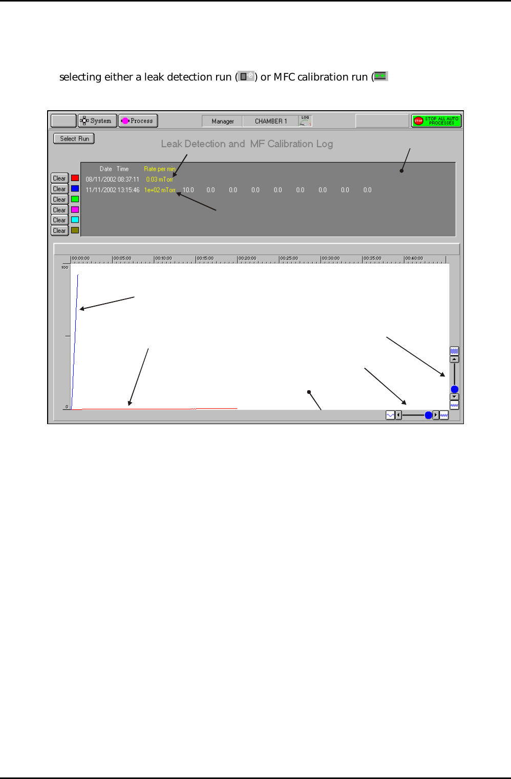
RKSKP= iÉ~â=ÇÉíÉÅíáçå=~åÇ=jc`=Å~äáÄê~íáçå=äçÖ=é~ÖÉ=
The leak detection and MFC calibration log page is accessed from the Select Run page by
selecting either a leak detection run (
) or MFC calibration run ( ) and then clicking on
the View Run button.
Log panel
Graph panel
Leak detection run
MFC Calibration run
Leak detection trace
(Red)
MFC calibration trace
(Blue)
Time axis scale controls
Pressure axis scale controls
Fig 5.7: Typical leak detection and MFC calibration log page
This page is used to view details of up to six leak check runs and/or MFC calibration runs. Note
that Fig 5.7 shows details of a leak test (red trace) and an MFC calibration run (blue trace).
The facilities available on this page are:
Select Run
button
Displays the Select Run page.
Clear buttons
Select to remove the associated data from the log panel and graph
panel. Note that to re-display the cleared data, you must return to the
Select Run page and re-select it.
Log panel Displays details of each run in text format.
Graph panel Displays a plot of each run (pressure versus time). Each run is
represented by a coloured trace as indicated by the palette displayed
adjacent to the run data in the Log panel. The graph can be scaled in
each axis by the controls located at the bottom-left corner of the
graph.
Operating Instructions
Printed: 22-Mar-06, 10:42 Page 5-29 of 52 UC Davis 94-721001 Issue 1: March 06
mä~ëã~ä~ÄpóëíÉãNMM lñÑçêÇ=fåëíêìãÉåíë=mä~ëã~=qÉÅÜåçäçÖó== System Manual
RKT= léÉê~íçê=~ÇàìëíãÉåíë=
RKTKN= j~åì~ä=~ÇàìëíãÉåí=çÑ=íÜÉ=oc=ã~íÅÜáåÖ=ìåáí=
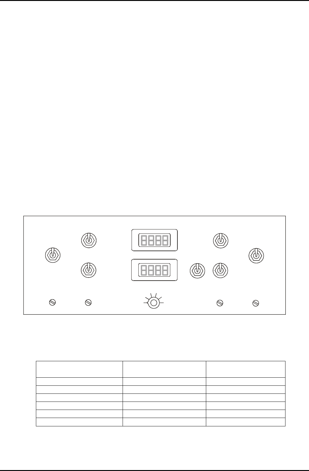
A manual adjustment panel, shown in Fig 5.8, is located behind a flap in the front of the
equipment rack. It comprises the following controls and indicators:
Auto / Manual switch: Sets the operating mode of the RF matching unit.
C1 MAX / MIN: Manual adjustment of RF matching capacitor C1. (Rotating its shaft
clockwise or counter clockwise.)
C2 MAX / MIN: Manual adjustment of RF matching capacitor C2. (Rotating its shaft
clockwise or counter clockwise.)
C1 PARK: Park position potentiometer for C1.
C2 PARK: Park position potentiometer for C2.
RF Interlock ON/OFF: Disables the RF interlock. RF generators deliver no power if the
interlock is off.
Capacitor positions for C1 and C2 are displayed as numbers from 000 (minimum) to 999
(maximum).
AUTO
AUTO
MANUAL
MANUAL
C1 MAX
C1 MAX
C1 MIN
C1 MIN
C2 MAX
C2 MAX
C2 MIN
C2 MIN
C1 PARK
C1 PARK
C2 PARK
C2 PARK
ON
OFF
RF
Interlock
C1
C2
1
2
3
4
5
6
DISPLAY SELECTO
R
Fig 5.8: Typical AMU control panel
Note that Fig 5.8 shows an AMU control panel with control facilities for two AMUs. The left-
hand side controls are for AMU1 and the right-hand side controls are for AMU2. The LCD
displays are switched using the DISPLAY SELECTOR switch as shown in the following table.
DISPLAY SELECTOR
POSITION
LCD 1 (UPPER) LCD 2 (LOWER)
1 AMU 1 C1 POSITION AMU 1 C2 POSITION
2 RF 1 FORWARD POWER RF 1 REFLECTED POWER
3 RF 1 SETPOINT RF 1 Hi/Lo
4 RF 2 FORWARD POWER RF 2 REFLECTED POWER
5 RF 2 SETPOINT SPARE
6 AMU 2 C1 POSITION AMU 2 C2 POSITION
For full details of the Oxford Instruments Plasma Technology AMU, refer to its Operation and
Maintenance manual in Volume 3 of this manual.
Operating Instructions
UC Davis 94-721001 Issue 1: March 06 Page 5-30 of 52 Printed: 22-Mar-06, 10:42
System Manual lñÑçêÇ=fåëíêìãÉåíë=mä~ëã~=qÉÅÜåçäçÖó== mä~ëã~ä~ÄpóëíÉãNMM
RKTKO= ^ÇàìëíáåÖ=íÜÉ=åáíêçÖÉå=êÉÖìä~íçê=çìíäÉí=éêÉëëìêÉ=
NOTE: Refer to Section 2 for a description of the Nitrogen vent distribution circuit.
The regulator outlet pressure should not usually require adjustment from its factory setting.
However, if adjustment is necessary, proceed as follows.
WARNING
THIS PROCEDURE INVOLVES WORKING ON THE SYSTEM WITH COVERS REMOVED
AND WITH THE ELECTRICAL POWER ON. THEREFORE IT MUST ONLY BE CARRIED OUT
BY TRAINED AND COMPETENT PERSONNEL WHO ARE AWARE OF THE RISKS
INVOLVED.
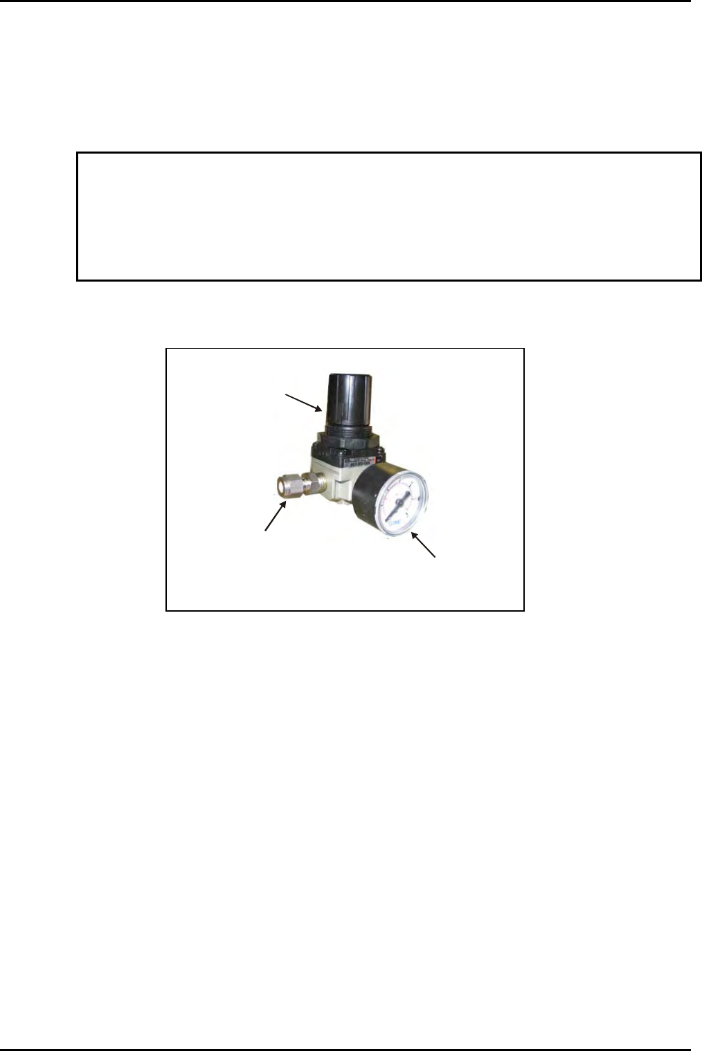
1) Remove system panels as necessary to gain access to the regulator.
Outlet connector
Outlet pressure
control knob
Outlet pressure
gauge
Fig 5.9: N
2
Pressure regulator/gauge
2) Adjust the regulator outlet pressure control knob to set the outlet pressure to the
maximum which will not open the check valve; normally 0.5 to 0.7 bar gauge as
indicated on the regulator gauge.
NOTE: Setting the outlet pressure too low will extend system venting times
excessively, and may compromise the purge gas flow to the turbo pump if
fitted. Setting the outlet pressure too high will open the check valve and
waste gas, but will not reduce venting times.
3) Refit all system covers.
4) Carry out a simple process to check that the vent sequence operates correctly.
Operating Instructions
Printed: 22-Mar-06, 10:42 Page 5-31 of 52 UC Davis 94-721001 Issue 1: March 06