00193794-11_VD_SSW 505.05_de en - 第49页
Software Version Description, Station Software 505.05 07/2008 Edition - The "Long PCB" option always applies to the entire line. - The placement machines do not need to be switched off to start processing long …
Software Version Description, Station Software 505.05 07/2008 Edition
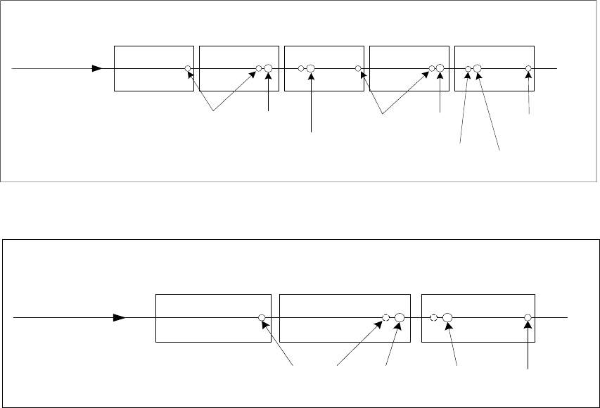
The two diagrams below each show one conveyor lane with two stop positions per processing area.
Transport direction
Proximity
switch
Bero
Stop
position 1
Proximity
switch
Stop
position 1
Stop
position 2
Input conveyor
Intermediate
conveyor
PA 1 PA 2 Output conveyor
Proximity
switch
Stop
position 2
Fig. 5-3: Conveyor track with two processing areas
Transport direction
Proximity
switch
Proximity
switch
Stop
position 1
Input conveyor
Processing
conveyor
Output conveyor
Stop
position 2
Fig. 5-4: Conveyor track with a single processing area
The following rules apply for the "Long PCB" option:
- If a global ink spot is defined, it must be possible to move to it in PA1, otherwise it is impossible
to decide whether to assemble the board or not.
- If position recognition is deactivated for subpanels and activated for the board, it must be
possible to move to the fiducials defined for the board in both processing areas.
- A subpanel can only be assembled in a processing area if it is possible to move to the
associated ink spot and the associated local fiducials, because
- it must be clear whether or not the subpanel is to be assembled before placement starts,
- the correction factors from the global position recognition must be known for placement.
All fiducials and ink spots for a subpanel must be located either completely in PA 1 or
completely in PA2.
- If placement of a component requires separate position correction, it must be possible to move
to all the fiducials defined for this placement position in the processing area in which the
component is to be placed.
- Fiducials can also be located outside the overlap region.
- Up to 6 fiducials must be defined for a fiducial set for a board.
48 of 150
Software Version Description, Station Software 505.05 07/2008 Edition
-
The "Long PCB" option always applies to the entire line.
- The placement machines do not need to be switched off to start processing long boards.
However, the line must be emptied and the stations must be provided with new machine data.
- If the programming system is used to switch the conveyor mode while there is no board in the
conveyor, the new conveyor mode applies to the next board to move into the input conveyor.
- If there are boards in the conveyor during reconfiguration, these are moved through using the
old conveyor mode. The new conveyor mode only applies as of the next board to move into the
input conveyor. This can, however, only be moved into the processing conveyor when none of
the old boards are in the conveyor.
- There can be N stop positions in each processing area. When creating the job in the
programming system, a specification is made as to the stop positions in a processing area in
which the board is stopped and processed.
- The programming system is used to configure which of the stop positions can be used by the
optimization function. During optimization, the stop positions are determined and passed to the
station with the job specification.
- The "Long PCB" option also applies to machines with a dual conveyor.
- If the "Long PCB" option is set, ”Whispering down the Line” is automatically disabled.
5.26.1 Restrictions
- "Whispering down the Line" and "Whispering down the Machine" are only possible if only
identical stop positions (with identical offsets) are used in a line.
- It is not possible to check whether a stop unit (stopper, laser light barrier) is installed in the
incorrect position. No checks are made other than fiducial recognition.
- Ink spot recognition is not possible in "synchronous dual conveyor" mode.
- It is only possible to teach the PCB reference position for a conveyor lane if a standard stop
position is present (offset 0).
- It is not possible to buffer a board between the input conveyor and the output conveyor in "Long
PCB" conveyor mode.
- When manipulating fiducials, the operator is responsible for ensuring that it is possible to move
to the fiducial to be taught by selecting the correct gantry.
- The distribution of the fiducial positions and the placement positions across the processing
areas is not checked at the station. It is assumed that the data from the programming system
has been specified correctly in this respect.
49 of 150

Software Version Description, Station Software 505.05 07/2008 Edition
5.26.2 Machine-specific restrictions
- If a stop unit other than the standard stop unit (not equal to 0) is used for a board, the board
handling of the conveyor firmware is switched to "Long PCB" internally.
- The conveyor firmware does not support stop units / stop positions with a negative offset.
- The conveyor firmware only supports the stop units which are physically present. A maximum of
2 stop units are taken into account in the interface to the conveyor.
- The following restrictions apply as a result of the existing hardware:
Machine type Possible number of
stop units in PA 1
Possible number of
stop units in PA 2
HF / HF/3 2 2
HS-50 / HS-60 1 2
S-25 HM / S-27 HM 1 --
5.27 Coplanarity module
The coplanarity module is supported in version 505.xx of the software.
The coplanarity module is used to check selected components for coplanarity or colinearity prior to
placement.
The coplanarity measurement system used is an optical inspection system. This has the job of
determining the offsets of the leads of a component with respect to the placement plane
(coplanarity) and the angle to the perpendicular (colinearity) and compare this with a specified
tolerance. A valid evaluation makes a statement as to whether all the measured lead offsets are
within the specified tolerances.
5.27.1 Restrictions
- Since the coplanarity module only works in conjunction with a stationary IC/FC sensor and a
Twin Head, it can only be used for HF and HF/3 machines.
- The coplanarity module can only be used in processing area 2 (location 3).
- Coplanarity measurement is not possible in conjunction with dipping.
- The current coplanarity measurement system does not support any parallel measurement
operations, i.e. a measurement operation (preparation and execution of the measurement) can
only ever be used for one segment of the Twin Head at a time.
- Coplanarity measurement is not supported in the package form manipulator.
- Only the coplanarity sensor ILD2000 is supported.
50 of 150