00193794-11_VD_SSW 505.05_de en - 第57页
Software Version Description, Station Software 505.05 07/2008 Edition 5.33.2 Requirements - Ink spots are always whispered. That applies both to the machine (WDTM – Whispering down the Machine) and to the line (WDTL – Wh…
Software Version Description, Station Software 505.05 07/2008 Edition
-
Mapping
There is no new mapping plate available with a width of 430 mm. This results in the following
restrictions:
If the machine zero point is moved outward, mapping is always carried out by means of
conveyor configuration ("Adjust position of fixed edge" Æ "Standard width"/"Excess width
HS60").
The maximum conveyor width in conjunction with the feature "flexible dual conveyor with
widened conveyor track" is 380 mm (not 430 mm) when "excess width HS60" is set for the
position of the fixed conveyor edge. This must be ensured by the conveyor firmware.
If the machine zero point is moved and "standard width" is set for the position of the fixed edge,
the maximum conveyor width in conjunction with the feature "flexible dual conveyor with
widened conveyor track" is only 330 mm (not 430 mm). This must be ensured by the conveyor
firmware.
If the machine zero point is moved outward, a mapping width of 508 mm is possible with the
single conveyor. The maximum conveyor widths must be ensured by the conveyor firmware.
- Programming system:
The "synchronous dual conveyor" feature is not supported in conjunction with the "wide
conveyor" feature, since the spacing of the PCB reference corners changes.
- Programming system/optimization:
Optimization does not take into account that the travel paths change with the feature.
5.33 Whispering of ink spots
In Version 505.03 the "whispering of ink spots" functionality (i.e. the forwarding of ink-spot data) is
available both for the line (WDTL) and in a machine with two processing areas (WDTM).
5.33.1 Requirements
- Whispering requires every station in the line to be equipped with PCB barcode readers.
- PCB barcode mode must be set both for the stations in the line and for the line itself in the
programming system.
- In whispering mode, the ink-spot recognition option must be activated on every station in every
processing area (PA).
56 of 150
Software Version Description, Station Software 505.05 07/2008 Edition
5.33.2 Requirements
- Ink spots are always whispered. That applies both to the machine (WDTM – Whispering down
the Machine) and to the line (WDTL – Whispering down the Line). The whispering of ink spots is
carried out incrementally.
- Subpanels and component fiducials are not whispered (either down the machine or down the
line).
- The machine options "PCB data transfer" (= WDTL) und "PCB transfer from PA 1" (= WDTM)
are no longer displayed as options that can be selected.
- Whispering of ink spots is also possible in connection with the "Long PCB" option.
- If PCBs are conveyed through a processing area without being processed (e.g. because a panel
is specified (Æ empty panel) or because of the incorrect orientation of the components, the
incremental whispering of ink spots is not interrupted.
5.33.3 Restrictions
- Whispering of ink spots is not possible in connection with the "Synchronous dual conveyor"
option.
- Whispering of ink spots is not possible in connection with the recovery placement feature.
- Machines for which "Transport through" is set in all processing areas interrupt the incremental
whispering of ink spots.
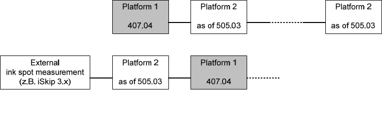
- The whispering of ink spots in mixed lines (platform 1 and platform 2 machines) is only possible
to a limited extent:
Permitted configuration of mixed lines 407.04 / 505.03
-
Whispering is not possible in lines with "productivity lift".
- In station-by-station downloading, all jobs must be specified with the same whisper mode.
57 of 150

Software Version Description, Station Software 505.05 07/2008 Edition
5.34 Cage resetting for THK guide
High-Force TwinHeads are equipped with a THK ball spline. For this guide type a cage resetting is
necessary after a certain cycle number. This resetting is perfomed by applying a certain force. The
force required for resetting the cage is reached when a nozzle is returned. In other words, every
time a nozzle is returned, the ball cage is reset.
If there is no nozzle change (and thus no cage resetting perfomed) after a certain number of
placement cycles, there is an additional nozzle change during PCB change.
5.34.1 Requirements
- Cage resetting is only carried out for the Twin Head.
- The cage can be reset for each segment independently.
- The number of placement cycles after the cage is reset is variable and is stored in the machine
database. Default value: 1000 placement cycles.
- Cage resetting can be activated/deactivated via the database; by default, it is activated.
- The cage can only be reset at a PCB change.
Reason: The processing of the PCB must not be interrupted by cage resetting for performance
reasons.
- A nozzle change or the returning of a nozzle counts as cage resetting.
Reason: The force required to reset the cage is obtained when the nozzle is removed from the
segment.
- If cage resetting could not be performed, the warning "Placement force could not be calibrated"
is displayed on the GUI.
5.34.2 Restrictions
- The customer must ensure that a nozzle changer (Twin) is configured and completely
calibrated.
- A cage reset is not carried out before or during the following processes:
- Calibration and mapping processes (SITEST)
- In the component shape manipulator (component testing)
- The counter is not incremented during these processes.
- The software draws no distinction between standard nozzles, special nozzles and grippers. It is
assumed that all of them can be changed automatically.
- A manual nozzle change, in which the operator removes the nozzle from the segment by hand,
is not considered to be a cage reset.
58 of 150