00193794-11_VD_SSW 505.05_de en - 第58页
Software Version Description, Station Software 505.05 07/2008 Edition 5.34 Cage resetting for THK guide High-Force TwinHeads are equipped with a THK ball spline. For this guide type a cage resetting is necessary after a …
Software Version Description, Station Software 505.05 07/2008 Edition
5.33.2 Requirements
- Ink spots are always whispered. That applies both to the machine (WDTM – Whispering down
the Machine) and to the line (WDTL – Whispering down the Line). The whispering of ink spots is
carried out incrementally.
- Subpanels and component fiducials are not whispered (either down the machine or down the
line).
- The machine options "PCB data transfer" (= WDTL) und "PCB transfer from PA 1" (= WDTM)
are no longer displayed as options that can be selected.
- Whispering of ink spots is also possible in connection with the "Long PCB" option.
- If PCBs are conveyed through a processing area without being processed (e.g. because a panel
is specified (Æ empty panel) or because of the incorrect orientation of the components, the
incremental whispering of ink spots is not interrupted.
5.33.3 Restrictions
- Whispering of ink spots is not possible in connection with the "Synchronous dual conveyor"
option.
- Whispering of ink spots is not possible in connection with the recovery placement feature.
- Machines for which "Transport through" is set in all processing areas interrupt the incremental
whispering of ink spots.
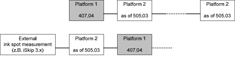
- The whispering of ink spots in mixed lines (platform 1 and platform 2 machines) is only possible
to a limited extent:
Permitted configuration of mixed lines 407.04 / 505.03
-
Whispering is not possible in lines with "productivity lift".
- In station-by-station downloading, all jobs must be specified with the same whisper mode.
57 of 150

Software Version Description, Station Software 505.05 07/2008 Edition
5.34 Cage resetting for THK guide
High-Force TwinHeads are equipped with a THK ball spline. For this guide type a cage resetting is
necessary after a certain cycle number. This resetting is perfomed by applying a certain force. The
force required for resetting the cage is reached when a nozzle is returned. In other words, every
time a nozzle is returned, the ball cage is reset.
If there is no nozzle change (and thus no cage resetting perfomed) after a certain number of
placement cycles, there is an additional nozzle change during PCB change.
5.34.1 Requirements
- Cage resetting is only carried out for the Twin Head.
- The cage can be reset for each segment independently.
- The number of placement cycles after the cage is reset is variable and is stored in the machine
database. Default value: 1000 placement cycles.
- Cage resetting can be activated/deactivated via the database; by default, it is activated.
- The cage can only be reset at a PCB change.
Reason: The processing of the PCB must not be interrupted by cage resetting for performance
reasons.
- A nozzle change or the returning of a nozzle counts as cage resetting.
Reason: The force required to reset the cage is obtained when the nozzle is removed from the
segment.
- If cage resetting could not be performed, the warning "Placement force could not be calibrated"
is displayed on the GUI.
5.34.2 Restrictions
- The customer must ensure that a nozzle changer (Twin) is configured and completely
calibrated.
- A cage reset is not carried out before or during the following processes:
- Calibration and mapping processes (SITEST)
- In the component shape manipulator (component testing)
- The counter is not incremented during these processes.
- The software draws no distinction between standard nozzles, special nozzles and grippers. It is
assumed that all of them can be changed automatically.
- A manual nozzle change, in which the operator removes the nozzle from the segment by hand,
is not considered to be a cage reset.
58 of 150
Software Version Description, Station Software 505.05 07/2008 Edition
5.35 Check of the holding-circuit vacuum
If the holding-circuit vacuum is too low, the components can slip out of position on the nozzle, thus
reducing placement accuracy and reliability.
The holding-circuit vacuum is essentially influenced by 2 factors.
- The height dependency of the vacuum values:
These can be adjusted by setting the vacuum parameters in the machine database.
- The distribution of the holding-circuit values when the valve tappets are open.
5.35.1 Requirements
The distribution of the holding-circuit vacuum is monitored automatically. If there are deviations, an
error message appears as a warning.
- The measurement results for the holding-circuit vacuum are evaluated after each placement
cycle.
- Only cycles in which no open segment has corrupted the measurement result are evaluated. All
cycles in which there are error messages are omitted from the evaluation:
- during optical centering (Vision)
- if vacuum problems occur (component not on nozzle before placement)
.
- If the evaluated vacuum is too low, the existing message "258 Holding circuit vacuum too low
(specified/actual)" is issued.
5.35.2 Restrictions
The error message "258 Holding circuit vacuum too low (specified/actual)" cannot be configured by
the operator as a fatal error.
59 of 150