00193794-11_VD_SSW 505.05_de en - 第78页
Software Version Description, Station Software 505.05 07/2008 Edition - Manual tray: Only for location 2 and location 4. - Component level indicator: The display of the boards which can be fit with the current component …

Software Version Description, Station Software 505.05 07/2008 Edition
-
Improved placement quality:
The vacuum check only works on modular DLM heads.
The vacuum check and the Z height check both depend on the nozzle. They only apply to the
nozzle types specified in the database.
The additional checks may lead to a higher rejection rate.
- SITEST test software:
Flexible dual conveyor: In order to be able to switch from a dual to single conveyor, mechanical
adaptations must be made.
- Traceability: Ist not possible to use umlauts for the board barcode.
- Fine calibration:
Fine calibration cannot be carried out if "Recovery Placement" mode is activated.
Fine calibration cannot be performed at locations 1 and 3.
Workaround: Carry out fine calibration at locations 2 and 4.
Fine calibration is not possible if an MTC has been attached.
Workaround: Remove MTC to carry out fine calibration and use a manual tray.
- The fine calibration can only be done for each gantry step by step (not for the whole machine in
one step) for the following machines: S-25HM, S-27HM, HS-50, HS-50+, HS-60.
- For the machines S-25HM and S-27HM the fiine calibration for 12-seg.C&P head has to be
done with ceram pads.
- For SIPLACE S27HM there is no fine calibration possible if a bero is installed as additional
stopper. Because the lightning unit can not be installed without restricting the pcb transport.
Note:
For further information, see the chapter "Supported feeders" in the software version description
for the SIPLACE Pro 2.0 programming system.
- Synchronous dual conveyor:
No ink spot recognition is available for synchronous dual conveyors.
- Mapping.
If multiple measurements are made during mapping, mapping will take approximately 4 to 5
times longer than previously.
- Diagnostics:
Not a feature of software version 505.
- Machine key switch:
Replaced by the menu command "Safe mode (Reduced speed)". Affects the main axes and the
star; ONLY with CLOSED cover.
- Short sleeve:
No software support (as for 504).
77 of 150
Software Version Description, Station Software 505.05 07/2008 Edition
-
Manual tray:
Only for location 2 and location 4.
- Component level indicator:
The display of the boards which can be fit with the current component configuration is only valid,
when the first board of a panel is finished.
- Multiple measurement (MFOV):
If only the outline of a component is described with the SIPLACE Pro programming system, the
position is only measured with the SIZE algorithm. Multiple measurement (MFOV) is not
possible with this algorithm. This can produce the following error on SIPLACE HF machines with
the stationary IC camera (type 22, field of view 40 x 50 mm):
If the size of the component is, for instance, 38 x 45 mm, it can be measured in the
manipulator at a pick-up angle of 0° (no multiple measurement), but not at a pick-up angle of 90°
(multiple measurement necessary). An identical error can occur when placing the component.
The placement angle is the critical issue here.
Remedy: If this error occurs, the component can be described with a row of leads for every
edge. To measure the position, the ROW algorithm must then be used.
- Twin Head nozzle changer:
Since the Twin Head nozzle changer is not an option, the nozzle cannot be changed manually
by acknowledging it.
Reason: The risk resulting from changing nozzles manually is that the nozzles are not seated
correctly. The Twin Head nozzle changer eliminates this risk.
- Number of package forms set 540:up multiplied by the number of configured sensor
systems is restricted to a maximum of
For any given job passed to the station, the number of package forms multiplied by the number
of sensor systems is not permitted to exceed 540.
Example: If 5 sensor systems are configured on the machine, then a maximum of 108 package
forms may be specified (108 x 5 = 540).
78 of 150
Software Version Description, Station Software 505.05 07/2008 Edition
-
Anti-crash circuit in PA1 at the HF (from series A-001):
In an HF/3, the anti-crash board applies a 15 V signal at an input port in order to query the
status of the anti-crash board. For the HF (from series A-001) (SW 505.02), the Logical
Subsystem I/O (LSSIO) has already been taken over from the 601 software. This means that
this port is queried. However, it is not possible to set a port to the status "low" or "high".
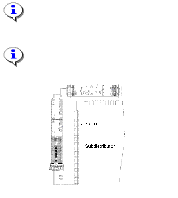
Workaround: A connector with a bridge between pin 1 and 4 is installed at connector No. X4 ra
(see fig. below) in the subdistributor of all HF machines (from series A-100). This sets the input
for the gantry distance to "high" at hardware level. Connector X4 ra was previously unused.This
connector is installed for system acceptance purposes and may not be removed.
Note:
This connector is installed for system acceptance purposes and may not be removed. If the
connector is removed, error messages relating to the gantry distance are output. This
connector is not installed at the standard HF and is not required there. Connector X4 ra
therefore continues to be unused in the HF.
Note:
For more details please refer to the technical information "Anti Crash Circuit in PB 1 at the HF
(from series A-001)" (44V01084).
Fig. 6-1: Connector X4 ra in the subdistributor
79 of 150