00190802-02.pdf - 第179页
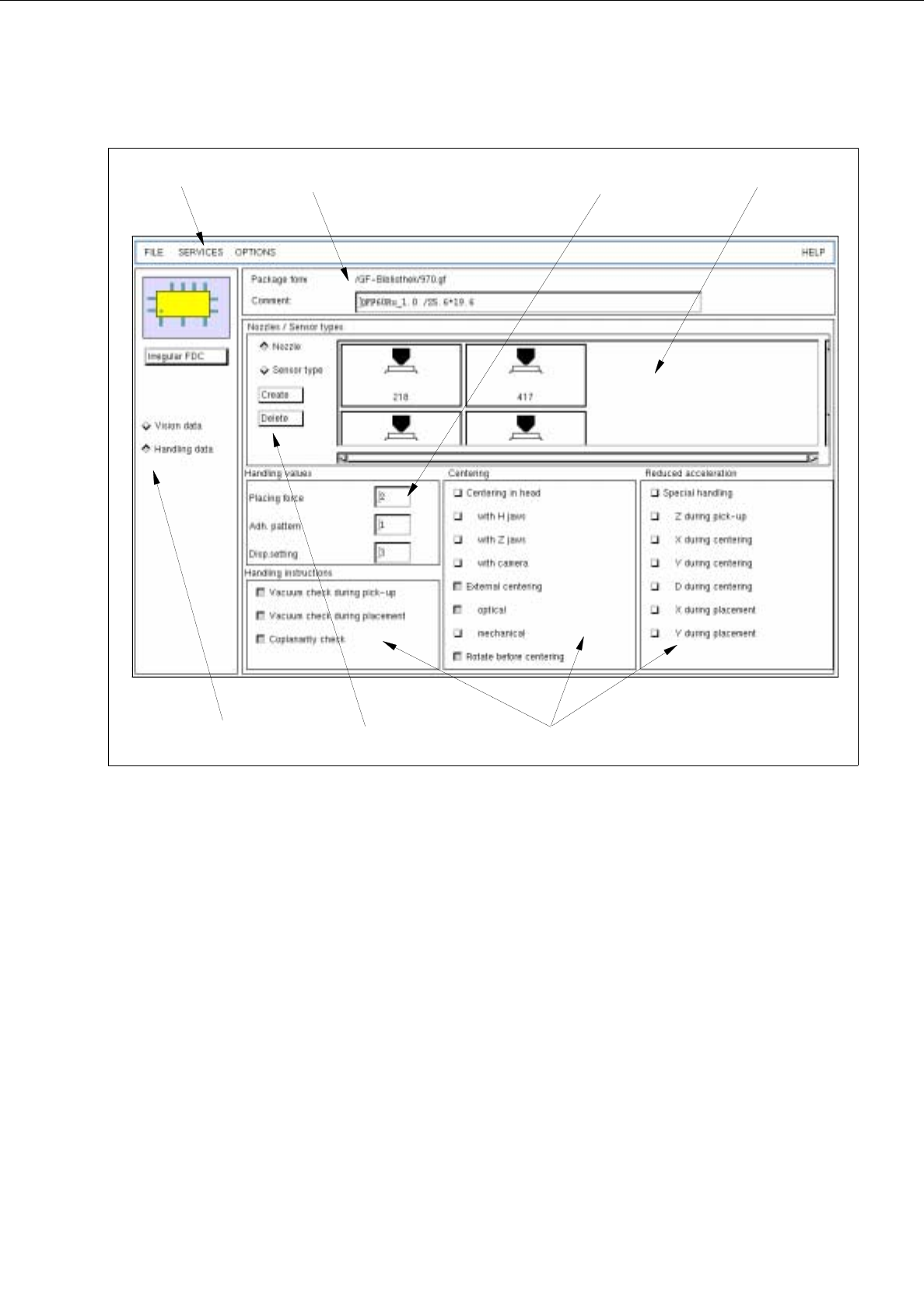
User’s Manual Line Computer UNIX 6 Product / Package Form Software Version 402.xx Edition 03/97 6.1 Package Form Editor 6 - 5 Fig. 6.1.4 Main Window " Pac kage Form Editor (Displa ying Handling Data - Irregular FDC)…
6 Product / Package Form User’s Manual Line Computer UNIX
6.1 Package Form Editor Software Version 402.xx Edition 03/97
6 - 4
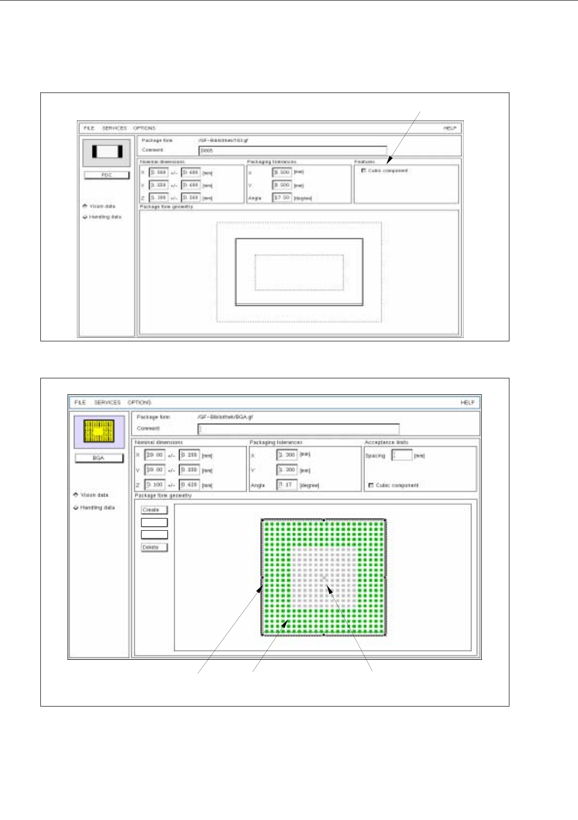
Fig. 6.1.2 Main Window "Package Form Editor (Displaying Vision Data - PDC)"
Fig. 6.1.3 Main window "Package Form Editor (Displaying Vision Data - BGA)"
selection field
(write-protected)
grid group ball
balls identified as
not available
Group
Pin/BGA
User’s Manual Line Computer UNIX 6 Product / Package Form
Software Version 402.xx Edition 03/97 6.1 Package Form Editor
6 - 5
Fig. 6.1.4 Main Window "Package Form Editor (Displaying Handling Data - Irregular FDC)"
The areas of the main window and their functions are explained in the following.
The main window of the Package Form Editor (displaying "Vision data" or "Handling data") is subdivided as
follows:
-
Title bar
-
Menu bar
-
Setting area
-
Selection fields
-
Command area
-
Editing area
-
Display area
selection fields
menu bar
command area
editing area
setting area
display areatitle bar
(write-protected)

6 Product / Package Form User’s Manual Line Computer UNIX
6.1 Package Form Editor Software Version 402.xx Edition 03/97
6 - 6
Title bar
The title bar displays the directory in which the selected package form (or the GF-file) is contained, and the
number of the package form.
In the editing field below the title bar it is possible to enter a comment, e.g. the package form assigned to the
GF-no. (No inverted commas or quotation marks will be accepted).
The comment can be modified at any time, i.e. even after the package form has been saved.
Menu bar
The menu bar contains the "FILE", "SERVICES", "OPTIONS" and "HELP" menus.
A complete description of the "SERVICES" menu is contained in section 6.1.2.1.
☞
NOTE
Since the functions and operation of the "FILE", "OPTIONS" and "HELP" menus are similar to those in other
application programs of the line computer, they are described comprehensively in chapt. 2.
Setting Area
The layout of the main window is determined by clicking on the buttons
Vision data
or
Handling data
.
In addition, the package form type (except for the "BGA" type) can still be changed at any time with the aid of
the <Package form type> button (see section 6.1.2.2).
Selection fields
(see section 6.1.2.3 and section 6.1.2.9)
With the setting
Vision data
the characteristics of the current component type can be selected (see section 6.1.2.3).
With the setting
Handling data
the type of processing appropriate for the current component type can be
defined (see section 6.1.2.9).
Command area
The commands that may have been activated in this area, in combination with the settings
FDC
or
BGA
and
Vision data
, enable pin groups and grid groups to be generated or deleted (see section 6.1.2.4). Moreover,
the window for the description of the model data or group data for a selected object (pin, group, ball, grid group)
can be opened. If setting Handling data has been selected, nozzles and sensor types can be generated or
deleted (see section 6.1.2.10).
Editing areas
(see section 6.1.2.5 and section 6.1.2.11)
If the
Vision data
setting has been selected, the dimensions of a package form (including its tolerances) are
defined by entering values in the respective editing fields of the editing areas. Moreover, the "cubic/non-cubic"
feature can be defined for FDCs and BGAs.
If
Handling data
setting has been selected, the placing force, the number of the adhesive pattern (which has
been defined for the current package form) and the adhesive amount to be dispensed can be entered.
☞
NOTE
If the current package form is a standard package form (numbers ranging from 1 ... 1500), only
the handling
data can be edited.
Display area
(see section 6.1.2.6)
If the
Vision data
setting has been selected, the current package form is displayed graphically in the display area
of the main window. After each change of the package form data the graphical image is automatically updated.
To change model or group data the respective graphic must be selected (see section 6.1.2.7).
If setting
Handling data
has been selected, all nozzles or sensor types generated are shown in the field "Nozzle
/ Sensor type" depending on the button that has been activated (see Fig. 6.1.4).