00190802-02.pdf - 第183页
User’s Manual Line Computer UNIX 6 Product / Package Form Software Version 402.xx Edition 03/97 6.1 Package Form Editor 6 - 9 6.1.2.4 Pac kage Form Editor Command Area - Setting "Vision dat a" ☞ NO TE The co mm…
6 Product / Package Form User’s Manual Line Computer UNIX
6.1 Package Form Editor Software Version 402.xx Edition 03/97
6 - 8
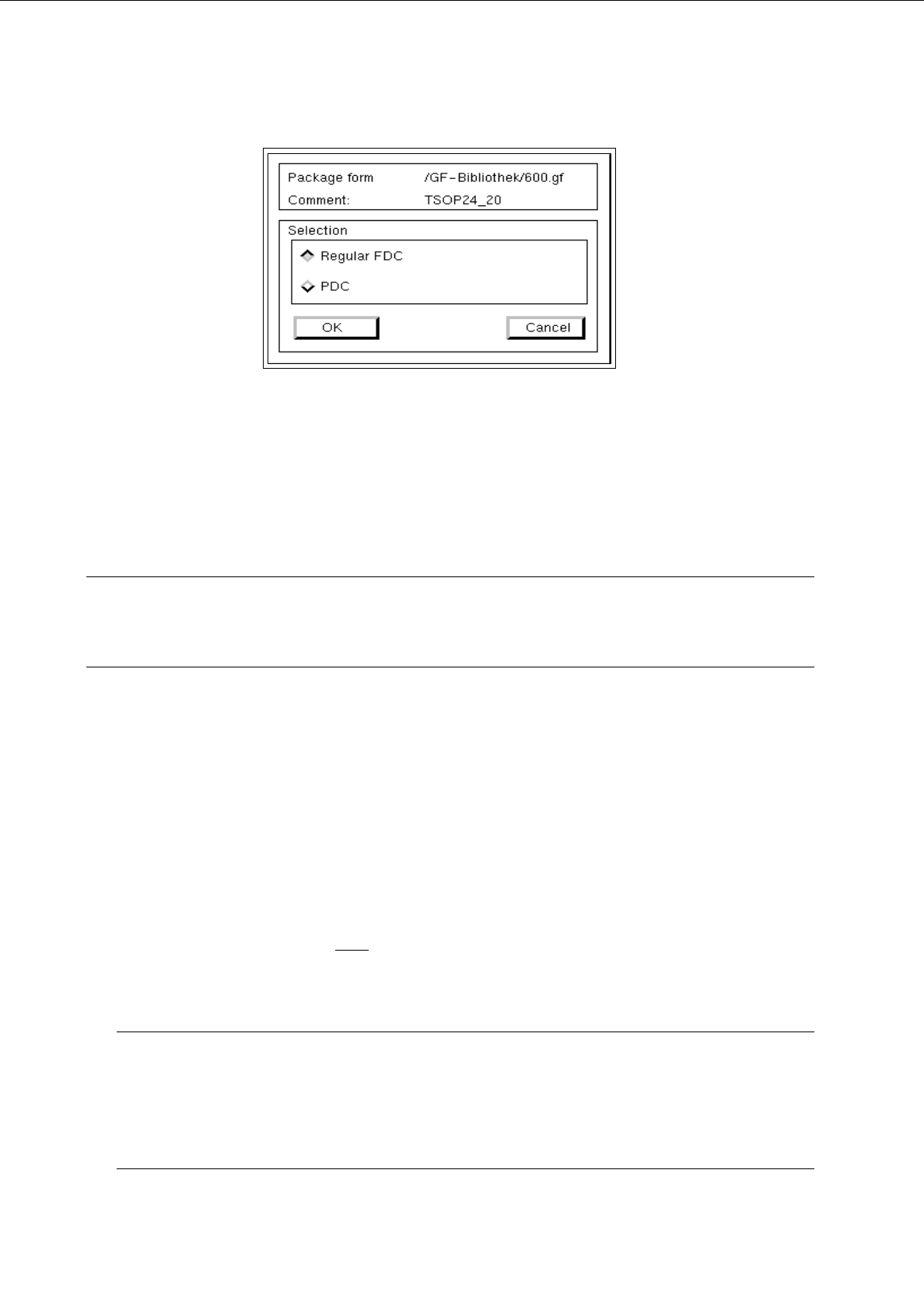
Depending upon whether the current package form is a PDC, a regular or irregular FDC, the following selection
possibilities for the new type are available:
-
A PDC can be converted into a regular or irregular FDC.
-
A regular FDC can be converted into an irregular FDC or a PDC.
-
An irregular FDC can be converted into a regular FDC or a PDC.
☞
NOTE
If the package form type is to be changed from an FDC to a PDC, a warning message is displayed
informing you that all model and group data will be deleted.
6.1.2.3 Selection Field "Features" (PDC) - Setting "Vision data"
-
Cubic component
The characteristic of the current package form can be set by means of the "Cubic component" button.
By default, this button is automatically activated when the Package Form Editor is opened. This
setting means that the current package form is of the cubic type and that the Vision System will have
to deal with sharply defined outlines.
The setting "Cubic component" must
be deactivated by clicking on the button whenever a cylindrical
package form is present.
☞
NOTE
If the current package form is a standard package form, the setting under Properties cannot be chan-
ged since the button is inactive.
In the case of FDCs and BGAs the "Cubic component" button is contained in the "Acceptance limits"
editing area.
User’s Manual Line Computer UNIX 6 Product / Package Form
Software Version 402.xx Edition 03/97 6.1 Package Form Editor
6 - 9
6.1.2.4 Package Form Editor Command Area - Setting "Vision data"
☞
NOTE
The command area is not displayed if the current package form is of the "PDC" type (see Fig. 6.1.2).
In the command area (see Fig. 6.1.1) only the "Create" command can initially be selected. The remaining
commands cannot be activated until an already-created pin or grid group is selected from the view area.
COMMANDS
The procedures for executing the commands are described in the following.
-
Create
A new pin group (see section 6.1.2.7) or a new grid group (see section 6.1.2.8) can be created.
●
Click on Create.
The window for the description of the new pin or grid group is opened (see Fig. 6.1.7 and
Fig. 6.1.11).
-
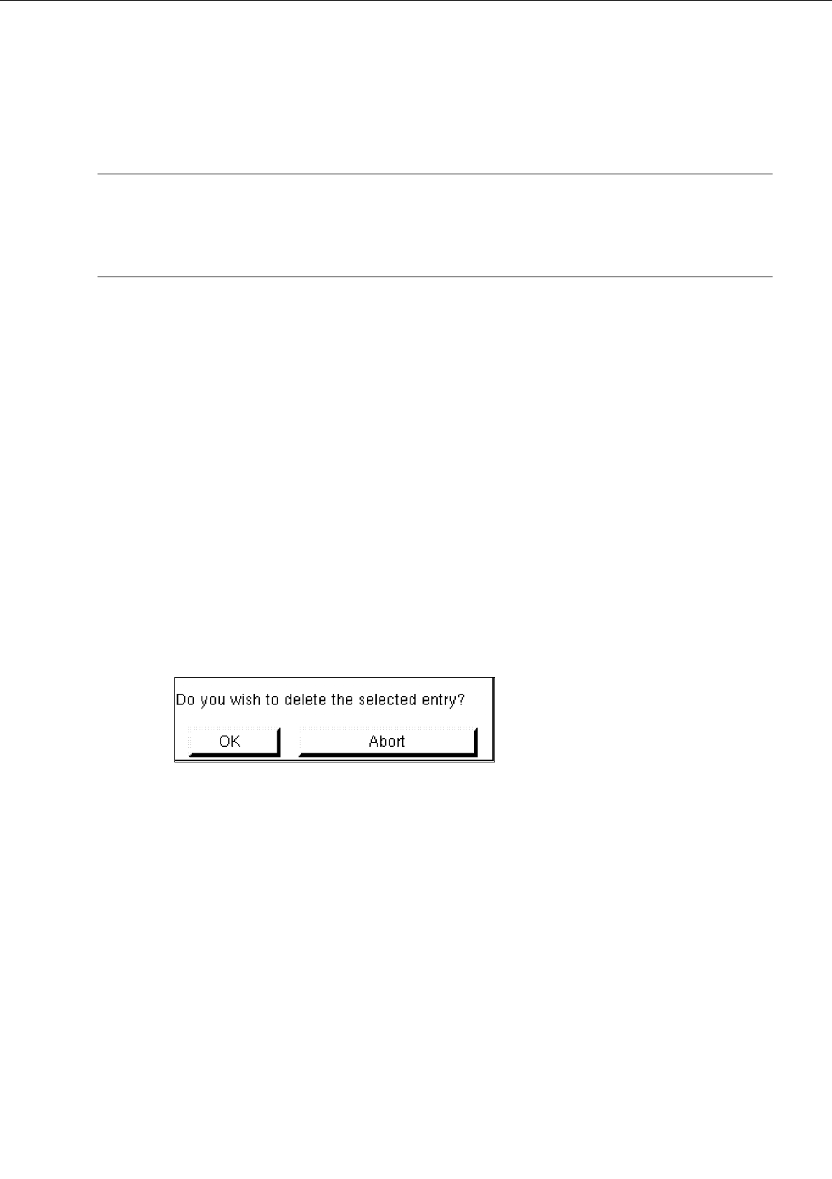
Delete
A selected pin or grid group can be deleted.
●
In the display area, select any pin or ball of the group you wish to delete. The selected group is
displayed, surrounded by a rectangle.
●
Click on Delete.
The following dialog box is opened.
●
Click on OK in the dialog box.
The dialog box is closed. The group is no longer displayed in the display area.
-
Group
This command permits the window for the description of the group data for a selected object (pin
group/grid group) to be opened.
●
From the view area select the group whose group data you wish to edit.
The selected group is surrounded by a rectangle.
●
Click on Group.
The window for the description of the group data is displayed on the screen (see Fig. 6.1.7 or
Fig. 6.1.11).

6 Product / Package Form User’s Manual Line Computer UNIX
6.1 Package Form Editor Software Version 402.xx Edition 03/97
6 - 10
-
Pin/Ball
This command permits the window for the description of the model data for a selected object
(pin/ball) to be opened.
●
From the view area select the group containing the object (pin/ball) whose model data you wish to
edit.
The selected group is surrounded by a rectangle.
●
Click on
Pin/Ball
.
The window for the description of the model data is displayed on the screen (see Fig. 6.1.8 or
Fig. 6.1.12).
6.1.2.5 Package Form Editor Editing Fields - Setting "Vision data"
☞
NOTE
When an existing GF-file is opened upon the start-up of the Package Form Editor, the factory or customer
defined default values are contained in the editing fields described below.
Editing field "Nominal dimensions"
-
X +/-
[mm] component length, with indication of the tolerances
see Fig. 6.1.5 or Fig. 6.1.9
-
Y +/-
[mm] component width, with indication of the tolerances
see Fig. 6.1.5 or Fig. 6.1.9
-
Z +/-
[mm] component height, with indication of the tolerances
see Fig. 6.1.6 or Fig. 6.1.9
☞
NOTE
The length of a component refers to the x-direction and its width to the y-direction since the position of the
component (in the Vision System) is so defined that "pin 1" is located at the bottom on the left (see Fig.
6.1.5 and Fig. 6.1.9).
Editing Area "Body"
☞
NOTE
This field is not
displayed if the current package form type is a "PDC" (see Fig. 6.1.2) or a "BGA" (see Fig.
6.1.3) since with these types the dimensions of the package body correspond to the nominal dimensions.
-
X
[mm] length of package body (see Fig. 6.1.6)
-
Y
[mm] width of package body (see Fig. 6.1.6)