00190802-02.pdf - 第188页
6 Product / Package Form User’s Manual Line Computer UNIX 6.1 Package Form Editor Software Version 402.xx Edition 03/97 6 - 14 Opening the window for ent ering or changing model data ● Select de sired p in or ball by (qu…

User’s Manual Line Computer UNIX 6 Product / Package Form
Software Version 402.xx Edition 03/97 6.1 Package Form Editor
6 - 13
6.1.2.6 Display Area - Setting "Vision data"
The current package form is graphically represented in the display area. When the dimensions are edited in
the "Nominal dimensions" and "Body" editing areas, the display is automatically updated.
-
The package (body) is drawn as a rectangle with a solid black line.
-
The two rectangles drawn with a broken black line reflect the nominal dimensions including negative
and positive tolerance values. (The nominal dimensions themselves are not displayed).
-
Created pin models are depicted as filled dark-blue rectangles in accordance with their length and
width dimensions. Their color changes depending on their state (see color explanation below).
-
Created ball models are depicted as filled dark-blue circles in accordance with their diameters. Their
color changes depending on their state.
Explanation of colors
Dark-blue pin/ball --> non-selected group for which a model is defined.
Gray-blue pin/ball --> non
-selected group for which no model has been defined yet.
Dark-green pin/ball --> selected group for which a model is defined.
Light-green pin/ball --> selected group for which no
model has been defined yet.
Single-click on a pin or a ball with the color
dark-blue or gray-blue --> draws a black frame around the group to which the clicked-on object
belongs.
The pins/balls contained in the selected group are displayed in
dark-green or light-green.
All pins/balls contained in the non-selected groups for which the same
model was defined, are displayed in dark-green.
Single-click on a pin or a ball with the color
dark-green or light-green --> reverses the selection
☞
NOTE
For the windows required for changing group or model data to open, the clicking sequence described below
must be observed.
Opening the window for changing group data
●
Single-click on any pin (see Fig. 6.1.1) or ball (see Fig. 6.1.3) of the desired group.
The whole group is highlighted.
●
Select pin or ball once more by (quickly) double-clicking.
The window for editing the group data is opened (see Fig. 6.1.7).

6 Product / Package Form User’s Manual Line Computer UNIX
6.1 Package Form Editor Software Version 402.xx Edition 03/97
6 - 14
Opening the window for entering or changing model data
●
Select desired pin or ball by (quickly) double-clicking.
The window for editing the model data is opened (see Fig. 6.1.8 and Fig. 6.1.12).
☞
NOTE
The window for editing the group or model data can also be opened using the commands "Group"
or "Pin/Ball" (see section 6.1.2.4).
6.1.2.7 Description of a Package Form of the Type "FDC"
For optical component centering by means of a Vision System, the package form of a component must be fully
described. In addition to entering the nominal dimensions and body dimension, (see section 6.1.2.5) the
following steps are required:
-
description of the pin groups
-
description of the pin models
For the performance of these steps, first the window for the description of the pin groups (see Fig. 6.1.7) is
opened. Only after a pin group has been defined can the window for the description of a pin model be opened
(see Fig. 6.1.8).
Explanation of Terms Used in GF-Data for the Description of Models and Groups of the "FDC"
Package Form Type:
-
Row
all pins on one side of the component
-
Model
pin shape
A model is defined by:
contact width
contact length
pin width and pin width tolerance
pin length and pin length tolerance
secondary offset of tips
-
Group
a group is a number of pins of the same model (pin shape)
A group is defined by:
number of pins
identical spacing
position of the group center (secondary and primary offset)
relative to the component center
(Each group is symmetric to the group center).
User’s Manual Line Computer UNIX 6 Product / Package Form
Software Version 402.xx Edition 03/97 6.1 Package Form Editor
6 - 15
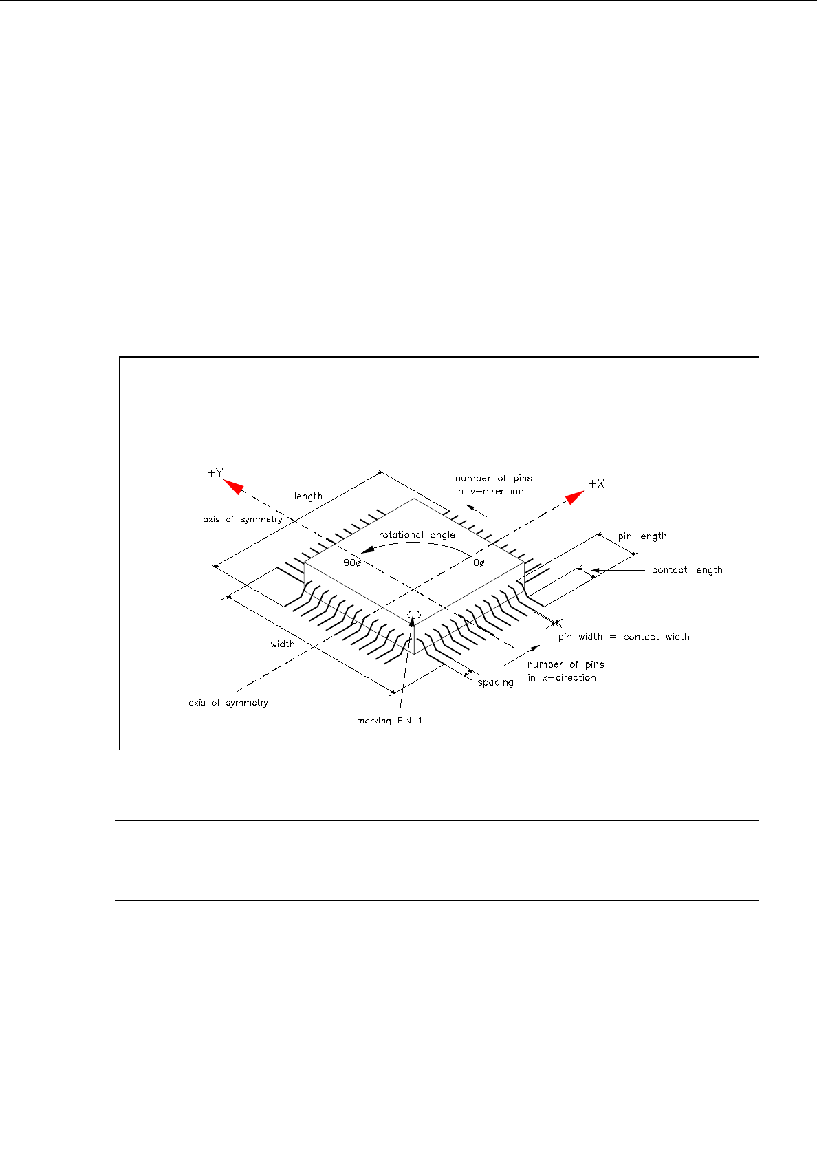
Criteria for components with regular pin configuration:
-
rectangular shape
-
only one pin model (pin shape)
-
identical number of pins in horizontal direction
-
identical number of pins in vertical direction
-
identical horizontal pin spacing
-
identical vertical pin spacing
-
identical pin contact length in horizontal direction
-
identical pin contact length in vertical direction
Fig. 6.1.5 Example "Regular Component"
☞
NOTE
For component centering by means of the Vision System, the component is placed on the optical cen-
tering station so that "pin 1" is visible in the left corner at the bottom of the monitor of the Vision System.