00190802-02.pdf - 第189页
User’s Manual Line Computer UNIX 6 Product / Package Form Software Version 402.xx Edition 03/97 6.1 Package Form Editor 6 - 15 Criteria for components wit h regular p in configura t ion: - recta ngular shap e - only one …

6 Product / Package Form User’s Manual Line Computer UNIX
6.1 Package Form Editor Software Version 402.xx Edition 03/97
6 - 14
Opening the window for entering or changing model data
●
Select desired pin or ball by (quickly) double-clicking.
The window for editing the model data is opened (see Fig. 6.1.8 and Fig. 6.1.12).
☞
NOTE
The window for editing the group or model data can also be opened using the commands "Group"
or "Pin/Ball" (see section 6.1.2.4).
6.1.2.7 Description of a Package Form of the Type "FDC"
For optical component centering by means of a Vision System, the package form of a component must be fully
described. In addition to entering the nominal dimensions and body dimension, (see section 6.1.2.5) the
following steps are required:
-
description of the pin groups
-
description of the pin models
For the performance of these steps, first the window for the description of the pin groups (see Fig. 6.1.7) is
opened. Only after a pin group has been defined can the window for the description of a pin model be opened
(see Fig. 6.1.8).
Explanation of Terms Used in GF-Data for the Description of Models and Groups of the "FDC"
Package Form Type:
-
Row
all pins on one side of the component
-
Model
pin shape
A model is defined by:
contact width
contact length
pin width and pin width tolerance
pin length and pin length tolerance
secondary offset of tips
-
Group
a group is a number of pins of the same model (pin shape)
A group is defined by:
number of pins
identical spacing
position of the group center (secondary and primary offset)
relative to the component center
(Each group is symmetric to the group center).
User’s Manual Line Computer UNIX 6 Product / Package Form
Software Version 402.xx Edition 03/97 6.1 Package Form Editor
6 - 15
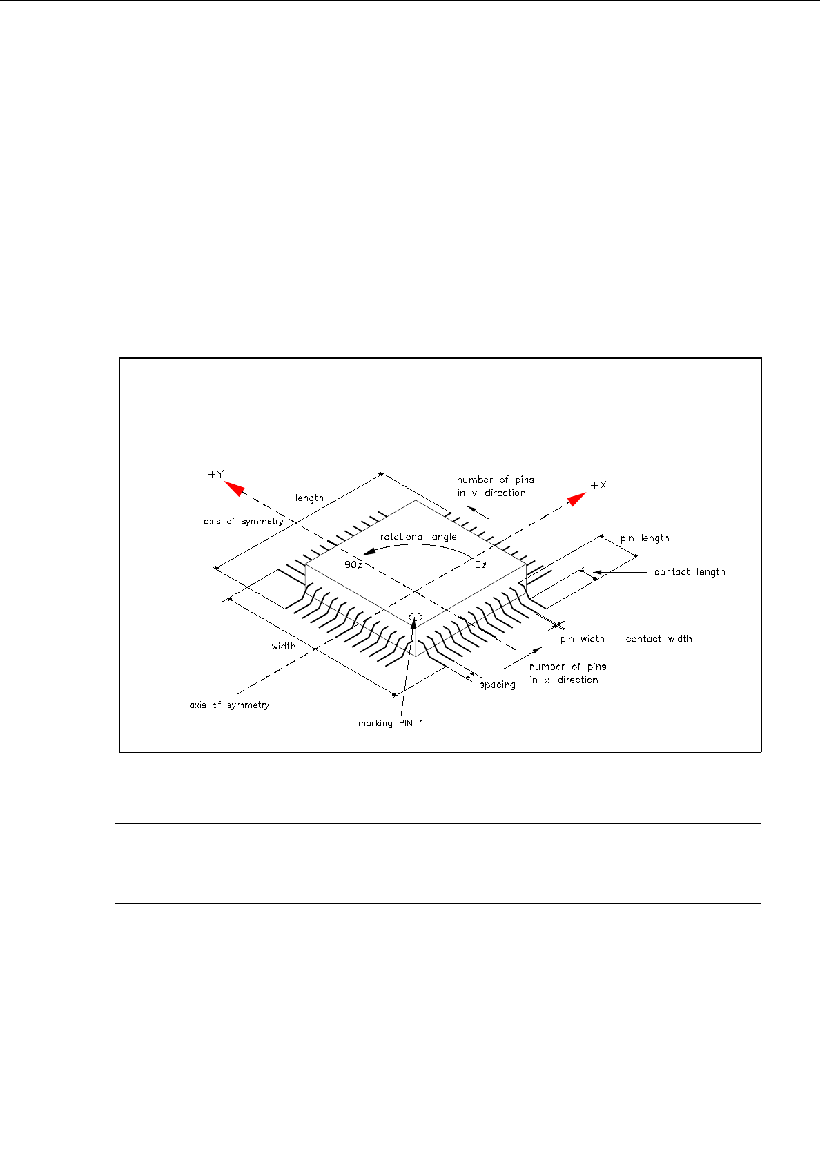
Criteria for components with regular pin configuration:
-
rectangular shape
-
only one pin model (pin shape)
-
identical number of pins in horizontal direction
-
identical number of pins in vertical direction
-
identical horizontal pin spacing
-
identical vertical pin spacing
-
identical pin contact length in horizontal direction
-
identical pin contact length in vertical direction
Fig. 6.1.5 Example "Regular Component"
☞
NOTE
For component centering by means of the Vision System, the component is placed on the optical cen-
tering station so that "pin 1" is visible in the left corner at the bottom of the monitor of the Vision System.
6 Product / Package Form User’s Manual Line Computer UNIX
6.1 Package Form Editor Software Version 402.xx Edition 03/97
6 - 16
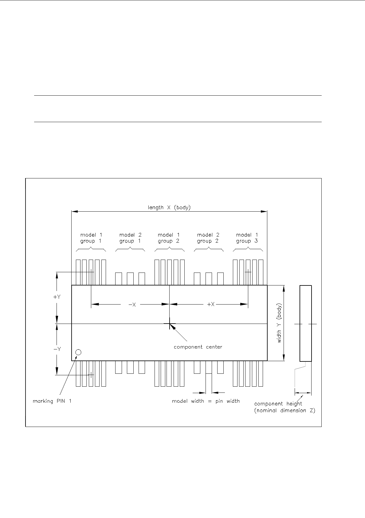
Criteria for components with irregular pin configuration:
-
rectangular shape
-
opposite pin rows (horizontal or vertical) may be different, i.e. need not be symmetrical.
☞
NOTE
The following criteria apply only to the placement of irregular components on HS-180 stations.
-
up to 3 different models (pin forms) in one row are possible.
-
in rows with 3 models a maximum of 15 pin groups can be described provided the width of any model
does not exceed the limit of 6mm.
Fig. 6.1.6 Example "Irregular Component"