00190802-02.pdf - 第203页
User’s Manual Line Computer UNIX 6 Product / Package Form Software Version 402.xx Edition 03/97 6.1 Package Form Editor 6 - 29 - External Cente ring The com ponent is centered ex ter nal ly by means of the optical o r me…

6 Product / Package Form User’s Manual Line Computer UNIX
6.1 Package Form Editor Software Version 402.xx Edition 03/97
6 - 28
6.1.2.9 Package Form Editor Selection Fields - "Handling data" Display
In the selection fields a button is located next to each "handling type" (see Fig. 6.1.4).
The required "handling type" can be activated or deactivated by clicking on the corresponding button.
Selection field "Handling instructions"
This field serves to define the type of handling a component type will be subjected to during the placement
cycle.
-
Vacuum test during pick-up When the component is picked up sensors are used to
check whether the component has been picked up.
-
Vacuum test during placement When the component is placed sensors are used to check
whether the component has been placed.
-
Coplanarity check The coplanarity laser module determines by means of co-
planarity measurement whether pins of the component
are bent and whether it may have to be discarded.
-
Good nozzle contact In the case of cubic components, this setting provides
good nozzle contact by means of adequate vacuum supply.
Selection field "Centering"
This selection field serves to define the type of centering suited for the component type. For this purpose, the
setting "Centering in head" or "External centering" can be chosen from. Moreover, the centering procedure for
the particular centering type can be defined.
- Centering in head
The component is centered in the placement head if any
one of the three following options is selected in addition.
with H jaws mechanical centering by means of h-jaws
(not possible on SIPLACE 80)
with Z jaws mechanical centering by means of z-jaws
(not possible on SIPLACE 80)
with camera optical centering by means of head camera
(not possible on HS-180)

User’s Manual Line Computer UNIX 6 Product / Package Form
Software Version 402.xx Edition 03/97 6.1 Package Form Editor
6 - 29
- External Centering
The component is centered externally by means of the
optical or mechanical centering station.
(Not possible on Siplace 80S).
optical The component is centered using the (external) optical
centering station.
mechanical The component is centered using the (external) mechanical
centering station.
(At present not operational)
Rotate before centering The component is turned (by 90° or 270°) prior to being
placed in the centering station.
Selection field "Reduced acceleration"
When the setting "Special handling" is activated in the selection field you can reduce the speed at which the
placement head moves when performing pick-up, centering or placement operations along the x, y, z and
d-axes. It is thus possible to handle and and place also large components (e.g. PLCC's 84) securely.
- Special handling
"Special handling" is defined for the pick-up, centering and
placement cycles of a component.
Z during pick-up reduced acceleration in z-direction when component
is picked up from its pick-up position
X during centering reduced acceleration in x-direction when component is
centered (at present not operational)
Y during centering reduced acceleration in y-direction when component is
centered (at present not operational)
D during centering reduced acceleration in d-direction (turning) when
component is centered
X during placement reduced acceleration in x-direction when component is
placed (deposited)
Y during placement reduced acceleration in y-direction when component is
placed (deposited)
6 Product / Package Form User’s Manual Line Computer UNIX
6.1 Package Form Editor Software Version 402.xx Edition 03/97
6 - 30
6.1.2.10 Package Form Editor Command Area - "Handling data" Display
In the command area (see Fig. 6.1.4) two different tools can be selected from (nozzle or sensor type) that can
be created or deleted by means of the corresponding commands. The desired tool type desired is selected by
clicking on the button adjacent to its name.
COMMANDS
The procedures to be followed for the execution of the commands are described in the following.
-
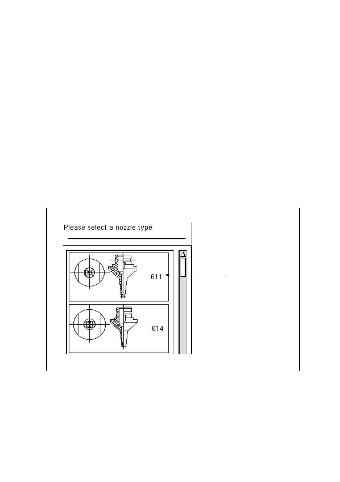
Create
This command can be used to create the nozzles and sensor types required for the current package
form.
●
Activate the button of the desired tool type.
●
Click on Create.
The selection window containing a list of all defined types of the selected tool type is opened.
Fig. 6.1.13 Selection Window of the "Nozzle Type"
nozzle type