00190802-02.pdf - 第227页
User’s Manual Line Computer UNIX 8 Product / PCB Software Version 402.xx Edition 06/96 8.1 PCB Editor 8 - 9 8.1 .3.1 FIL E M enu ☞ NO TE Only the fir st menu option of the menu is des cribed in the following. The funct i…

8 Product / PCB User’s Manual Line Computer UNIX
8.1 PCB Editor Software Version 402.xx Edition 06/96
8 - 8
Menu bar
The menu bar contains the "FILE", "SERVICES" and "HELP" menus.
The function of the "Copy PCB" menu option of the "FILE" menu is explained in more detail in section 8.1.3.1.
A complete description of the "SERVICES" menu is contained in section 8.1.3.2.
☞
NOTE
Since the functions and operation of the "FILE" and "HELP" menus are similar to those in other application
programs of the line computer, they are described comprehensively in chapter 2.
Display area
In the display area the selected PCB can be displayed in two different ways, depending on the currently active
"mode":
-
Upon opening, the editor is initially in the
"Structure Mode"
(see Fig. 8.1.4). In this mode, the name and the
structure of the loaded PCB are displayed. To be able to manipulate the PCB´s structure, the individual
partial PCB structures must be selected by clicking with the mouse.
-
If the editor is in the
"Graphic Mode"
(see Fig. 8.1.6) the entire PCB (depending on the selection of the ele-
ments, see section 8.1.3.4) is displayed graphically, including all placement positions, fiducials, ink spots,
coordinate systems, etc. If the offset values of at least one substructure are not completely defined, a
"structure graphic" is displayed in addition to the display of the PCB (see Fig. 8.1.7).
Command Area
Every command in this area is symbolized by an icon. If a partial PCB structure has been selected in the display
area, it can be manipulated by means of the activated command (see section 8.1.3.3).
Setting area
If the Structure Editor is in the Graphic Mode (see Fig. 8.1.6), different display options can be set using the
selection possibilities offered in this area (see section 8.1.3.4).
User’s Manual Line Computer UNIX 8 Product / PCB
Software Version 402.xx Edition 06/96 8.1 PCB Editor
8 - 9
8.1.3.1 FILE Menu
☞
NOTE
Only the first menu option of the menu is described in the following. The functions of the remaining options of
this menu are described in chapter 2.
-
Copying PCB
This function makes it possible to duplicate a currently loaded PCB. All predefined data (placement
positions, cluster, fiducials) will also be copied.
●
Activate icon in the command area.
●
Click on the uppermost partial PCB structure of the PCB structure (see Fig. 8.1.4).
●
Select menu option FILE --> Copy PCB.
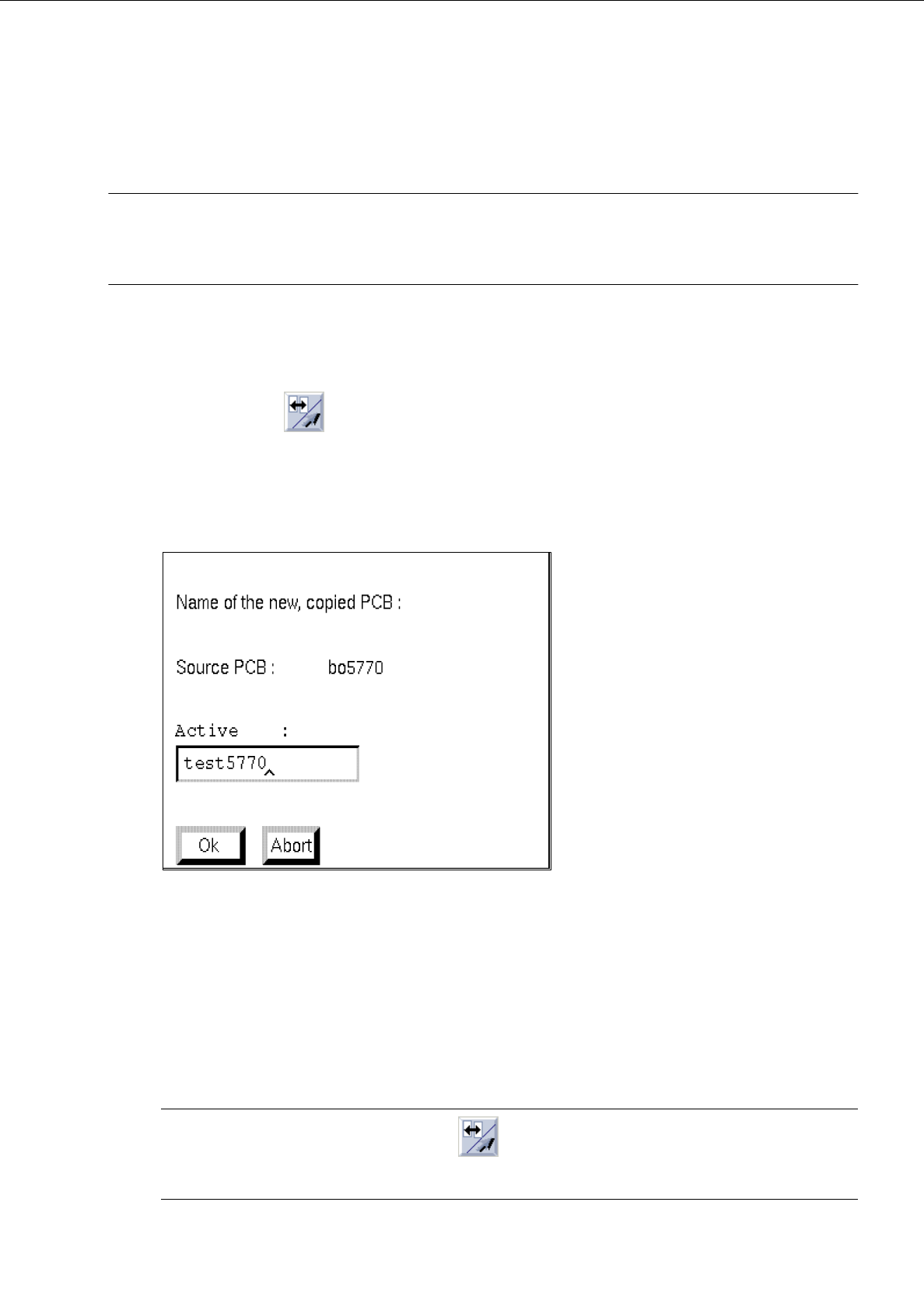
The following dialog box appears:
●
Enter the name and confirm with OK.
A second window of the Structure Editor containing the name of the new PCB and the copied
structure are displayed on the screen.
8.1.3.2 SERVICES Menu
The menu options of this menu serve to open the sub-editors for the definition of the cluster data and placement
positions. Moreover, it is possible to toggle between the Structure Mode and Graphic Mode display types.
☞
NOTE
Prior to invoking a menu function, the icon (Connect/Menu) in the command area must be
activated (see Fig. 8.1.4).

8 Product / PCB User’s Manual Line Computer UNIX
8.1 PCB Editor Software Version 402.xx Edition 06/96
8 - 10
-
Call up the
Placement Position Editor
for the definition of placement positions (only possible in the
Structure Mode)
●
In the display area select partial PCB structure with a mouse-click.
●
Select
SERVICES
-->
Placement Position Editor
.
The window of the Placement Position Editor (see Fig. 8.1.11) is opened.
-
Call up the
Cluster Editor
for the definition of the cluster data (only possible in the Structure Mode)
●
In the display area select partial PCB structure with a mouse-click.
●
Select
SERVICES
-->
Cluster Editor
The window of the Cluster Editor (see Fig. 8.1.8) is opened.
-
Structure Mode
This menu option serves to switch the view area from the Graphic Mode to the Structure Mode.
●
Select
SERVICES
-->
Struct. mode
The view area is switched to the Structure Mode (see Fig. 8.1.4).
-
Graphic Mode
This menu option serves to switch the view area from the Structure Mode to the Graphic Mode.
●
Select
SERVICES
-->
Graph. mode
The view area is switched to the Graphic Mode (see Fig. 8.1.6).
-
Call up the
Structure Editor
for the processing of a new PCB
●
Select
SERVICES
-->
Structure Editor...
.
The FSB for the selection of a new PCB is opened (see page 8 - 6).
●
Select PCB and confirm with
OK
.
The structure of the selected PCB is displayed in the display area of the new window.
Or (to obtain an empty window for a new PCB):
●
Enter new name.
The window of the Structure Editor is opened under the name of the new PCB.
8.1.3.3 Command Area of the Structure Editor (Structure Mode)
The commands are symbolized by means of icons. If an icon is activated by clicking upon it, the respective
action can be performed on a partial PCB structure subsequently to be selected.
☞
NOTE
The procedures and results of some of the commands described in the following are shown as examples
in Fig. 8.1.5 where the numbers 1 or 2 indicated in the circles represent the sequence of the steps to be
performed; the structures represented as broken lines stand for the results.