00190802-02.pdf - 第229页
User’s Manual Line Computer UNIX 8 Product / PCB Software Version 402.xx Edition 06/96 8.1 PCB Editor 8 - 11 Fig. 8.1.5 Examples "Usage and Results of s ome Commands in the Str ucture Editor"

8 Product / PCB User’s Manual Line Computer UNIX
8.1 PCB Editor Software Version 402.xx Edition 06/96
8 - 10
-
Call up the
Placement Position Editor
for the definition of placement positions (only possible in the
Structure Mode)
●
In the display area select partial PCB structure with a mouse-click.
●
Select
SERVICES
-->
Placement Position Editor
.
The window of the Placement Position Editor (see Fig. 8.1.11) is opened.
-
Call up the
Cluster Editor
for the definition of the cluster data (only possible in the Structure Mode)
●
In the display area select partial PCB structure with a mouse-click.
●
Select
SERVICES
-->
Cluster Editor
The window of the Cluster Editor (see Fig. 8.1.8) is opened.
-
Structure Mode
This menu option serves to switch the view area from the Graphic Mode to the Structure Mode.
●
Select
SERVICES
-->
Struct. mode
The view area is switched to the Structure Mode (see Fig. 8.1.4).
-
Graphic Mode
This menu option serves to switch the view area from the Structure Mode to the Graphic Mode.
●
Select
SERVICES
-->
Graph. mode
The view area is switched to the Graphic Mode (see Fig. 8.1.6).
-
Call up the
Structure Editor
for the processing of a new PCB
●
Select
SERVICES
-->
Structure Editor...
.
The FSB for the selection of a new PCB is opened (see page 8 - 6).
●
Select PCB and confirm with
OK
.
The structure of the selected PCB is displayed in the display area of the new window.
Or (to obtain an empty window for a new PCB):
●
Enter new name.
The window of the Structure Editor is opened under the name of the new PCB.
8.1.3.3 Command Area of the Structure Editor (Structure Mode)
The commands are symbolized by means of icons. If an icon is activated by clicking upon it, the respective
action can be performed on a partial PCB structure subsequently to be selected.
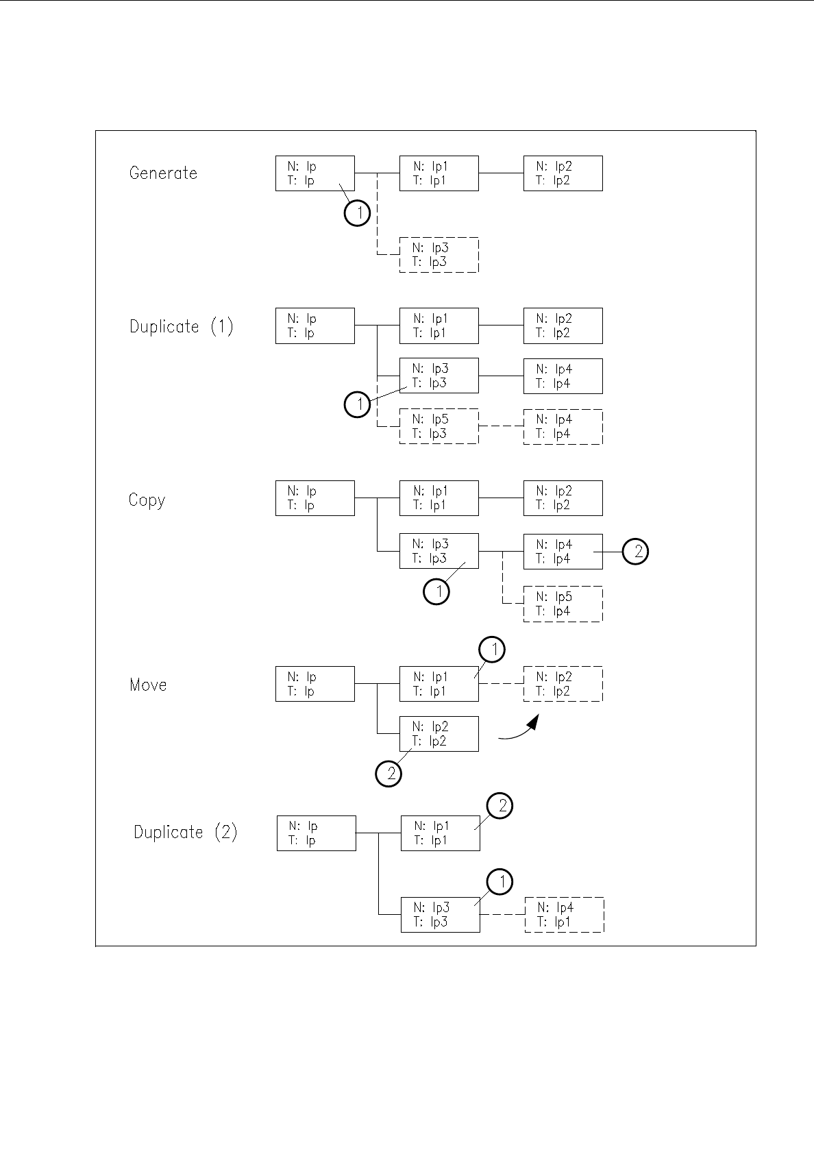
☞
NOTE
The procedures and results of some of the commands described in the following are shown as examples
in Fig. 8.1.5 where the numbers 1 or 2 indicated in the circles represent the sequence of the steps to be
performed; the structures represented as broken lines stand for the results.
User’s Manual Line Computer UNIX 8 Product / PCB
Software Version 402.xx Edition 06/96 8.1 PCB Editor
8 - 11
Fig. 8.1.5 Examples "Usage and Results of some Commands in the Structure Editor"
8 Product / PCB User’s Manual Line Computer UNIX
8.1 PCB Editor Software Version 402.xx Edition 06/96
8 - 12
-
Connect/Menu
This command serves to generate a new partial PCB structure containing a cross-reference to a PCB
type sharing common features with other partial PCB structures. The new PCB differs from this PCB
type only in that its coordinates are different. All other data are identical.
●
Activate icon .
●
Click on target PCB type.
●
Click on source PCB type.
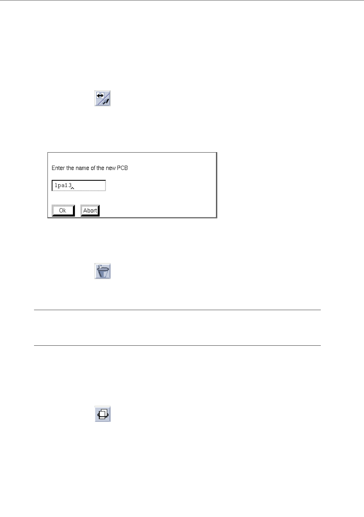
The following dialog box is opened.
●
Enter the name and confirm with
OK
.
-
Deleting
a partial PCB structure
●
Activate icon .
●
Select PCB structure with a mouse-click.
The partial PCB structure is deleted (without confirmation!).
CAUTION!
"Delete" is to be deactivated by selecting another command, as otherwise all other PCB types that are
subsequently clicked on will also be deleted.
-
Duplicating
a partial PCB structure
Existing cross-references to a given PCB type can be duplicated from a PCB partial structure thus
generating a new partial structure. Except for the coordinates, the data of the duplicated partial PCB
structure are identical.
●
Activate icon .
●
Select partial PCB structure.
The dialog box for entering the name is displayed.
●
Enter the name and confirm with
OK
.