00190802-02.pdf - 第237页
User’s Manual Line Computer UNIX 8 Product / PCB Software Version 402.xx Edition 06/96 8.1 PCB Editor 8 - 19 8.1.3.6 Display of PP-Data in the Structure Editor (Graphic Mode) The data of a sele cted pl acement position c…
8 Product / PCB User’s Manual Line Computer UNIX
8.1 PCB Editor Software Version 402.xx Edition 06/96
8 - 18
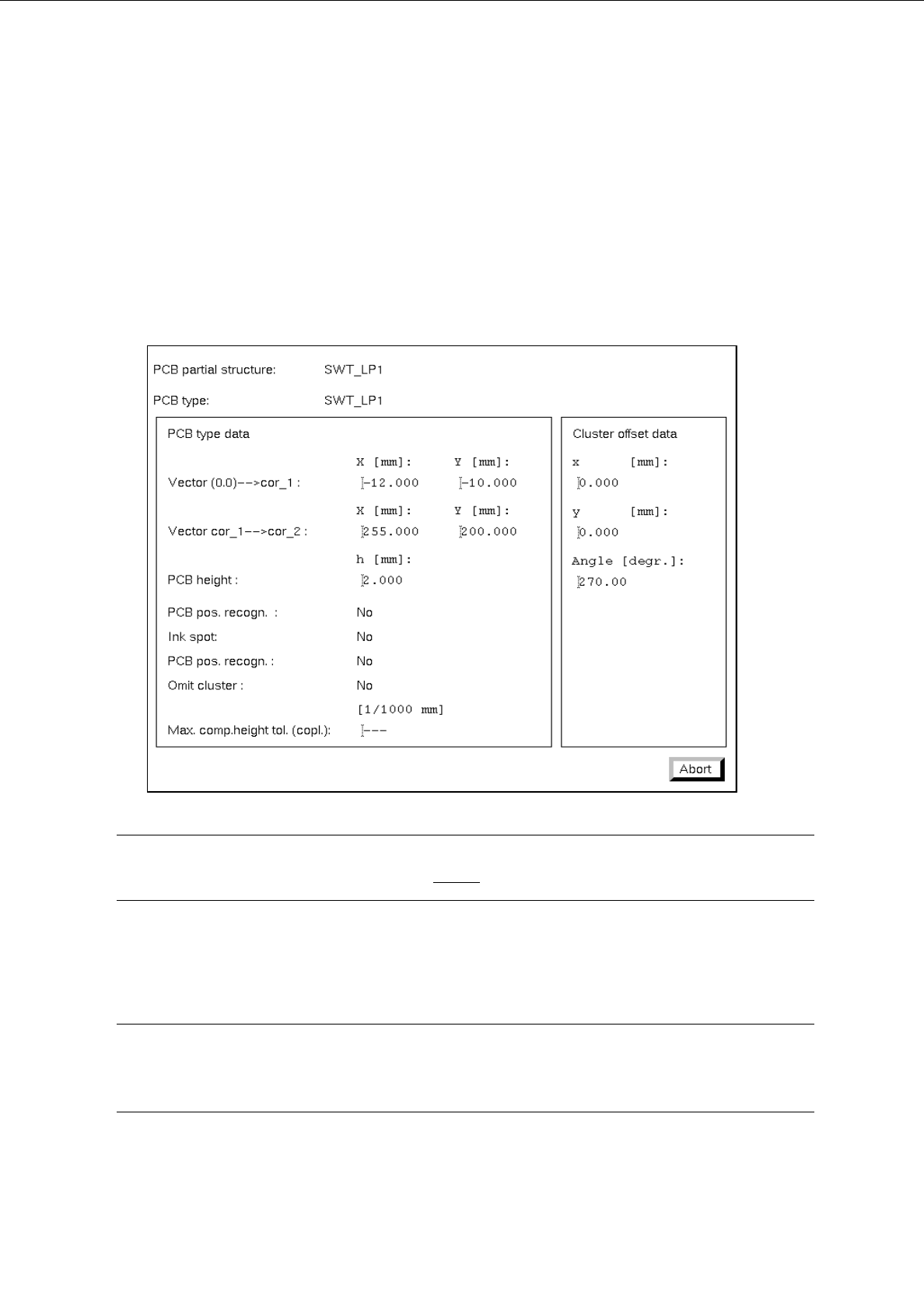
8.1.3.5 Display of the Cluster Data in the Structure Editor (Graphic Mode)
In the Graphic Mode of the Structure Editor the cluster data of the PCB and those of every substructure can
be displayed in separate windows.
●
Select the outline of the PCB structure by double-clicking on it.
The outline is highlighted by a selection frame in bold type.
The "PCB info" window containing the cluster data of the selected structure is opened.
☞
NOTE
The data contained in the "PCB info" window cannot be changed.
●
Click on the Abort button.
The "PCB info" window is closed.
☞
NOTE
In addition, the "PCB info" window can be opened for a substructure from the "PP information"
window (see page 8 - 19).
User’s Manual Line Computer UNIX 8 Product / PCB
Software Version 402.xx Edition 06/96 8.1 PCB Editor
8 - 19
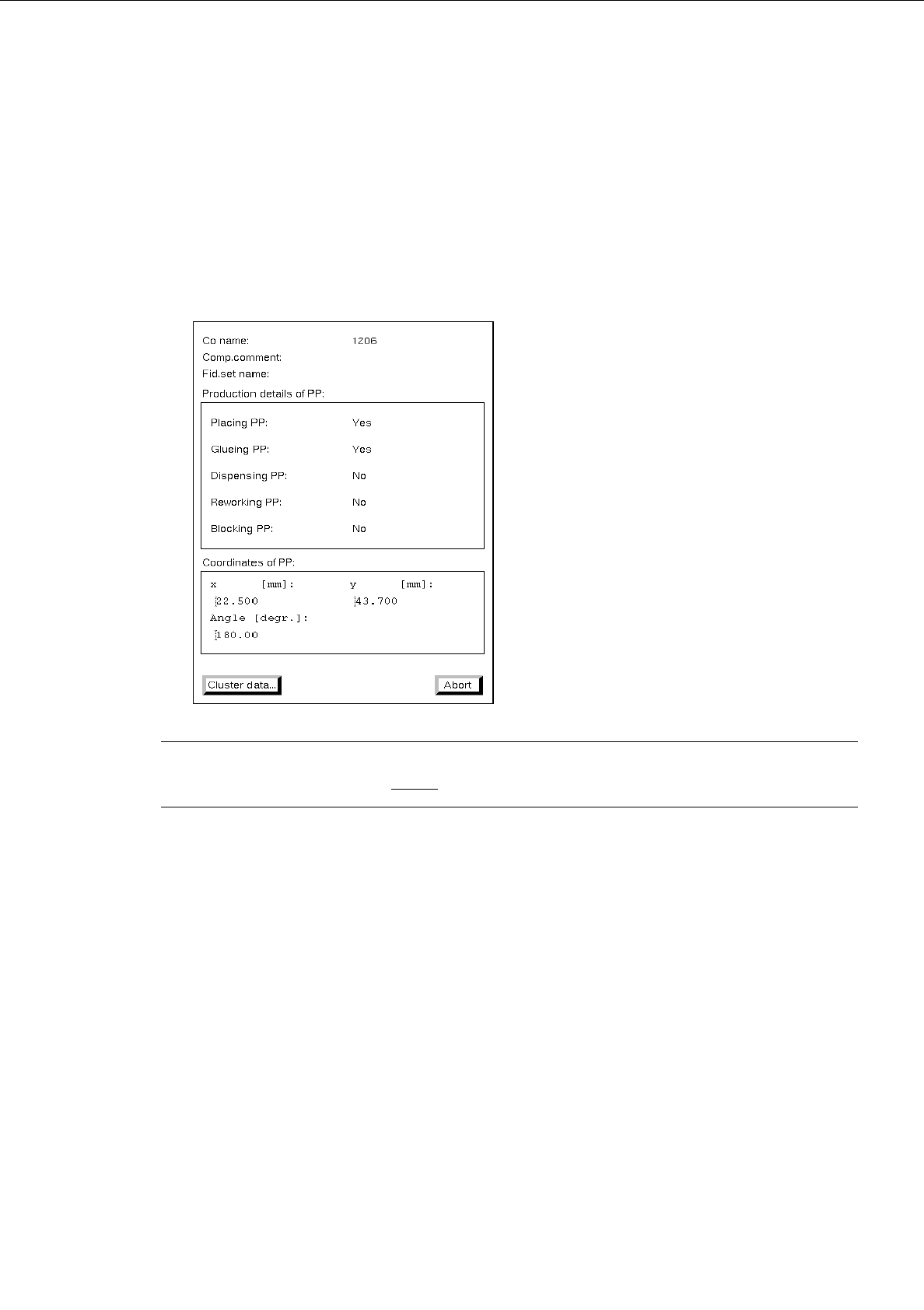
8.1.3.6 Display of PP-Data in the Structure Editor (Graphic Mode)
The data of a selected placement position can be displayed in a separate window in the Graphic Mode of the
Structure Editor.
●
Select the desired placement position by double-clicking.
The placement position is surrounded by a frame in bold type.
The "PP information" window containing the data of the selected placement position is opened.
☞
NOTE
The data in the "PP information" cannot be changed.
-
Cluster data...
This button permits the "PCB info" window to be opened that contains the cluster data of the sub-
structure in which the selected placement position is located.
●
Click on the Cluster data... button.
The "PCB info" window is opened.
●
Click on the Abort button in the "PCB info" window.
The "PCB info" window is closed.
●
Click on the Abort button in the "PP information" window.
The "PP information" window is closed.
8 Product / PCB User’s Manual Line Computer UNIX
8.1 PCB Editor Software Version 402.xx Edition 06/96
8 - 20
8.1.3.7 Colors and Their Meanings in the Structure Editor (Graphic Mode)
In the Graphic Mode of the Structure Editor several colors are used for the graphical elements displayed.
Depending on the status of the graphical elements (e.g. "blocked") the colors the colors have a different
meaning.
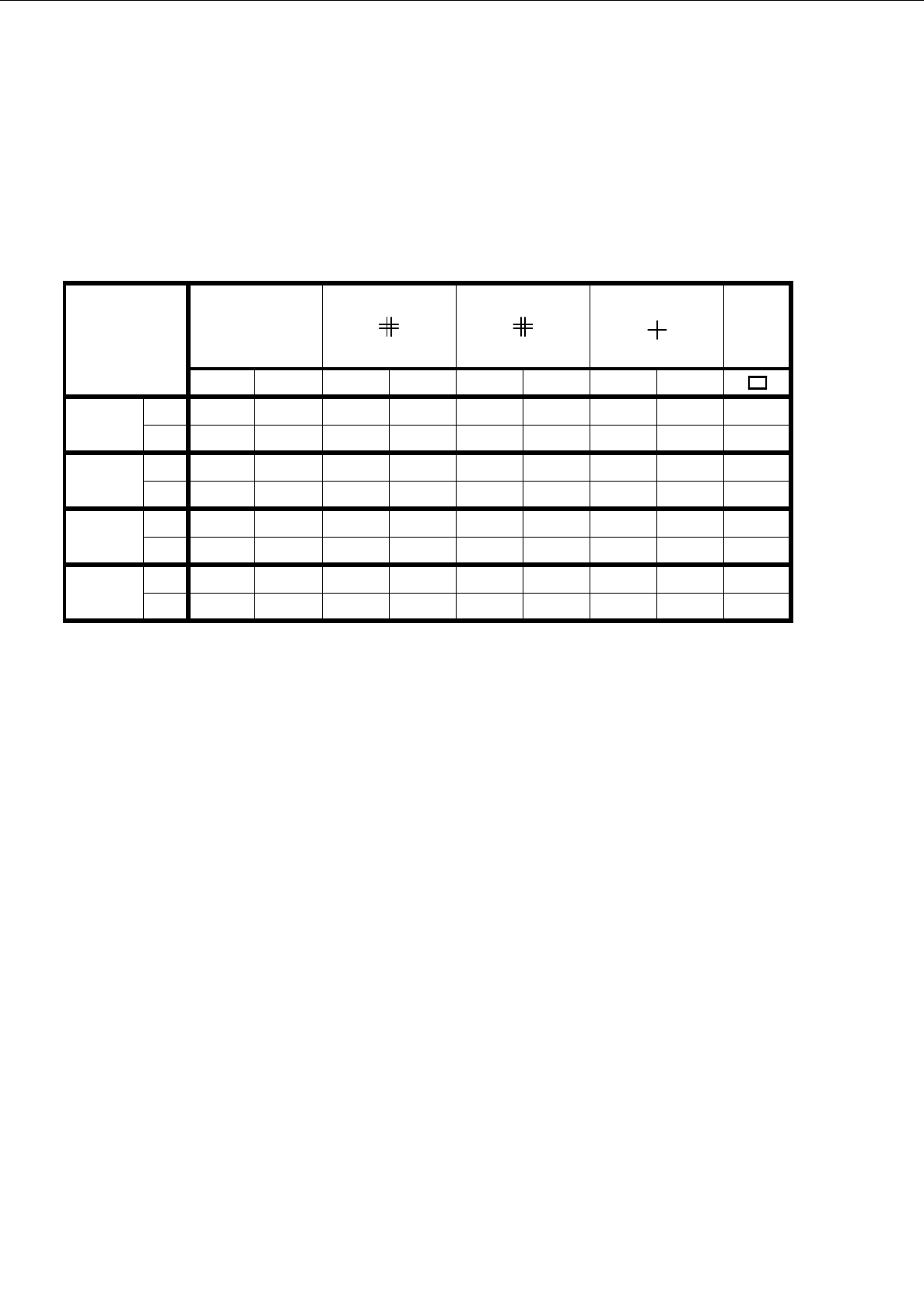
In the chart below the assignment of the colors to the status of the graphical elements displayed is shown.
Meaning of the colors:
-
black indicates that this object is valid, i.e. effective, with respect to the respective substructure.
-
gray indicates that this object is ineffective, i.e. owing to its own individual attribute, e.g.
blocked fiducial or ink spot.
-
red indicates that this object is only ineffective on account of production details, e.g. a fiducial
is not blocked, yet PCB position recognition is turned off.
-
green identifies the valid placement positions
Meaning of the Colors in the Structure Graphic:
-
black the offset data of the substructure and all of its higher-level substructures are defined.
The substructure is already displayed in the Graphic Mode.
-
red the offset data of the substructure are completely defined, not however, those of all supe-
rior substructures thereof. The substructure is not displayed in the Graphic Mode yet.
-
gray the offset data of the substructure have not been completely defined yet. The substructure
is not displayed yet in the Graphic Mode, and any possible display of its lower-level sub-
structures is suppressed.
Cluster data Ink spot
●
PCB fiducial PP fiducial
PP pos.
Outline
blocked normal blocked normal blocked normal blocked normal
Ink spot
recocnition
yesgrayblack-------
nograyred-------
PCB pos.
recognition
yes--grayblack-----
no--grayred-----
PP pos.
recognition
yes----grayblack---
no----grayred---
Omitting
cluster
no------graygreenblack
yes------grayredred
Tab. 8.1 - 1 Colors and symbols and their meanings