00190802-02.pdf - 第502页
17.1 Introduction User’ s Manual SIPLACE Line Computer UNIX 17.1.1 F rom the Placement Program to t he Assembly - Ov erview Software V ersion 402.xx Edit ion 06/96 17 - 2 Set-up gen eration Line con trol The adhe sive pa…
User’s Manual SIPLACE Line Computer UNIX 17.1 Introduction
Software Version 402.xx Edition 06/96
17 - 1
Using three PCBs as an example, this chapter contains a description of all work steps required - from the ge-
neration of the placement programs through to job scheduling.
This chapter can be used as a beginner´s guide for the new operator and be worked through step-by-step, or
it can serve as a reference or a refresher section for experienced programmers. All this is accomplished by the
two-page concept with the left side containing only keywords and the right side describing each work step in
detail.
The chapter is intended as a supplement to the other chapters of the User´s Manual and therefore cannot an-
ticipate every possible circumstance that may be of interest. For further information about a topic or a function,
please refer to the corresponding chapter in the User´s Manual.
In addition, it is very helpful to use the On-Line Help systems available:
—
On-line Bubble-Help:
contains information about all editing fields, icons and window areas.
• Click on the
Online Help On/Off
option on the
HELP
menu.
• Move the mouse pointer to the location where you wish to obtain explanations.
A window containing the Help information is opened and closed again by moving the mouse pointer.
—
Help Index:
contains a description on how to proceed concerning almost all topics.
• Click on the
Index
option on the
HELP
menu.
The Help Index is opened.
• Search for a topic using the
Text search
function, or browse through the contents and descriptions on
the topics by clicking on the terms highlighted in green.
The PCBs described relate to different learning objectives:
• PCB 1: single circuit, with focus on the basic principle of the generation of placement programs;
• PCB 2: single circuit, with focus on the description of customer-specific package forms;
• PCB 3: complex circuit, with focus on cluster technique.
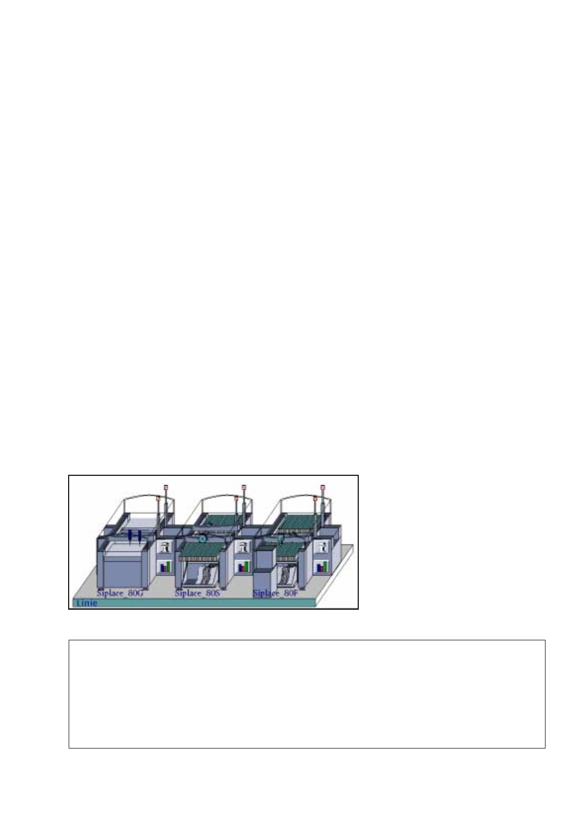
All examples are based on a given line and station configuration. Since the configuration differs from customer
to customer, the data given can be used as an example only and must be adapted by the customers to satisfy
their individual requirements.
Station Configuration
17. Practical Tips on Using the LC UNIX
17.1 Introduction
Siplace_80G :
• optical PCB centering
Siplace_80S:
• optical PCB centering
• revolver head
• segment type 2 -> 6xx nozzles
• component camera 19x25 in head
-> sensor type 9
Siplace_80F:
• optical PCB centering
• IC-head -> 4xx nozzles
• IC-head camera -> sensor type 7
• revolver head
• segment type 2 -> 6xx nozzles
• component camera 19x25 in head
-> sensor type 9
• Waffle-Pack Changer
Line Configuration
17.1 Introduction User’s Manual SIPLACE Line Computer UNIX
17.1.1 From the Placement Program to the Assembly - Overview Software Version 402.xx Edition 06/96
17 - 2
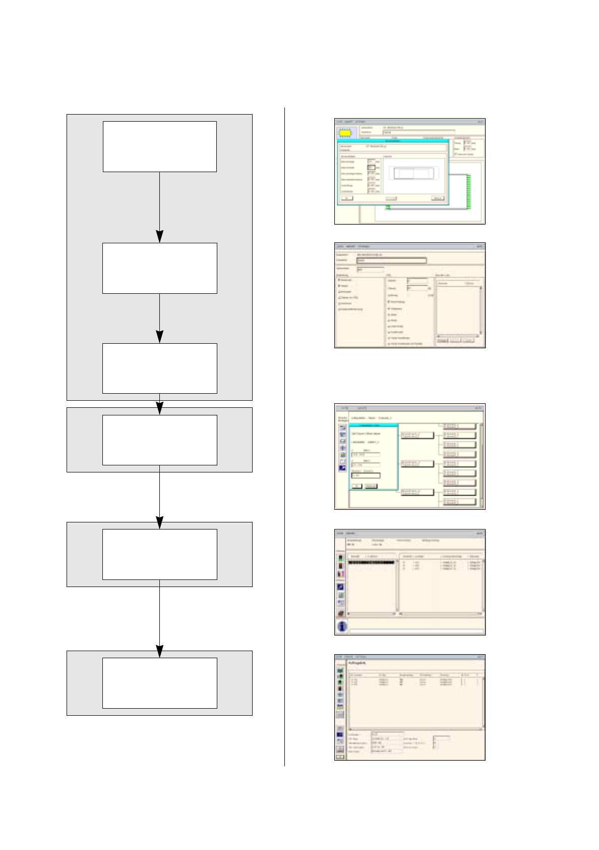
Set-up generation
Line control
The adhesive pattern description is dispensed with.
17.1.1 From the Placement Program to the Assembly - Overview
Description of a component
Component
description
Package form(GF)
description
PCB
description
Adhesive pattern
description
User’s Manual SIPLACE Line Computer UNIX 17.2 Description of Components and PCBs
Software Version 402.xx Edition 06/96 17.2.1 PCB 1: single circuit
17 - 3
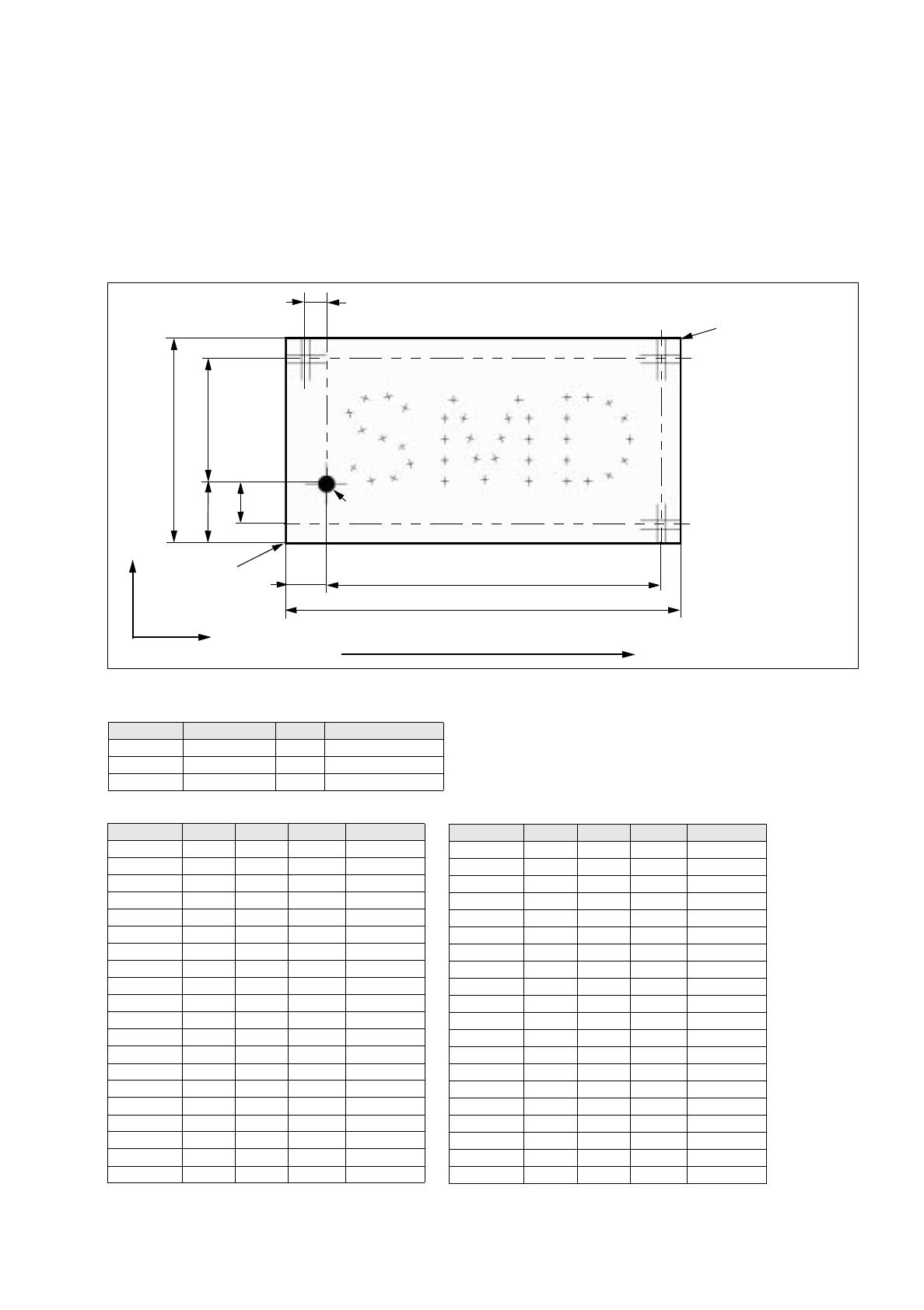
PM 1 PM 3
PM 2
PCB zero point
Comp.name X Y Angle Comment
Comp1 6.60 3.84 57.00 Pos1
Comp1 10.92 0.79 10.00 Pos2
Comp1 16.26 1.30 337.00 Pos3
Comp1 20.32 4.85 276.00 Pos4
Comp1 18.29 8.92 37.00 Pos5
Comp1 13.72 10.95 22.00 Pos6
Comp1 8.64 12.98 28.00 Pos7
Comp1 5.59 17.05 94.00 Pos8
Comp1 9.40 20.60 161.00 Pos9
Comp1 14.99 21.11 190.00 Pos10
Comp1 19.05 18.32 249.00 Pos11
Comp2 28.70 0.54 270.00 Pos14
Comp2 28.70 5.62 270.00 Pos15
Comp2 28.70 10.70 270.00 Pos16
Comp2 28.70 15.78 270.00 Pos17
Comp2 30.73 20.35 180.00 Pos18
Comp2 33.27 15.78 253.00 Pos19
Comp2 34.77 10.92 253.00 Pos20
Comp2 36.24 6.06 253.00 Pos21
Comp2 38.35 1.04 270.00 Pos22
96
50
10
15
81
30
17.2 Description of Components and PCBs
17.2.1 PCB 1: single circuit
PCB 1 is a single circuit with three different components. The package forms have been taken from the stan-
dard package form library. For PCB position recognition, three fiducials are available. Fiducial 48.pm is used
which must exist in the Master data/MVS-Bibliothek (if it is not available it must be taught, see Station Computer
User´s Manual).
Comp2 40.80 6.11 288.00 Pos23
Comp2 42.37 10.95 288.00 Pos24
Comp2 43.94 15.78 288.00 Pos25
Comp2 46.48 20.35 180.00 Pos26
Comp2 49.02 15.78 270.00 Pos27
Comp2 49.02 10.70 270.00 Pos28
Comp2 49.02 5.62 270.00 Pos29
Comp2 49.02 0.54 270.00 Pos30
Comp3 58.17 0.54 180.00 Pos31
Comp3 58.17 5.62 270.00 Pos32
Comp3 58.17 10.70 270.00 Pos33
Comp3 58.17 15.78 270.00 Pos34
Comp3 58.17 20.86 180.00 Pos35
Comp3 63.25 20.86 180.00 Pos36
Comp3 68.33 19.49 210.00 Pos37
Comp3 72.04 15.78 240.00 Pos38
Comp3 73.41 10.70 270.00 Pos39
Comp3 72.04 5.62 300.00 Pos40
Comp3 68.33 1.90 330.00 Pos41
Comp3 63.25 0.54 180.00 Pos42
Comp.name X Y Angle Comment
Direction of travel
X
Y
10
5
Corner 2
PCB coordinate
system 0°
Tab. 17.2-2: Placement Positions PCB 1
Tab. 17.2-1: Component Data PCB 1
Name Package form GF-No. Handling
Comp1.be SOT23 400 Glueing, Placing
Comp2.be 1206 105 Glueing, Placing
Comp3.be 0805 103 Glueing, Placing
PCB height = 1.5 mm
Fig. 17.2.1 Dimensions of PCB 1
Corner 1