slau358q.pdf - 第15页
www.ti.com Programming MSP Flash Devices Using the MSP Gang Programmer 15 SLAU358Q – September 2011 – Revised October 2019 Submit Documentation Feedback Copyright © 2011–2019, Texas Instruments Incorporated Operation det…
Programming MSP Flash Devices Using the MSP Gang Programmer
www.ti.com
14
SLAU358Q–September 2011–Revised October 2019
Submit Documentation Feedback
Copyright © 2011–2019, Texas Instruments Incorporated
Operation
2.1.1 Programming Using Interactive Mode
Use the following sequence to start the MSP Gang Programmer GUI and program MSP Flash Devices
using the Interactive Mode:
1. Click on the MSP Gang Programmer icon located in the program group that was specified during
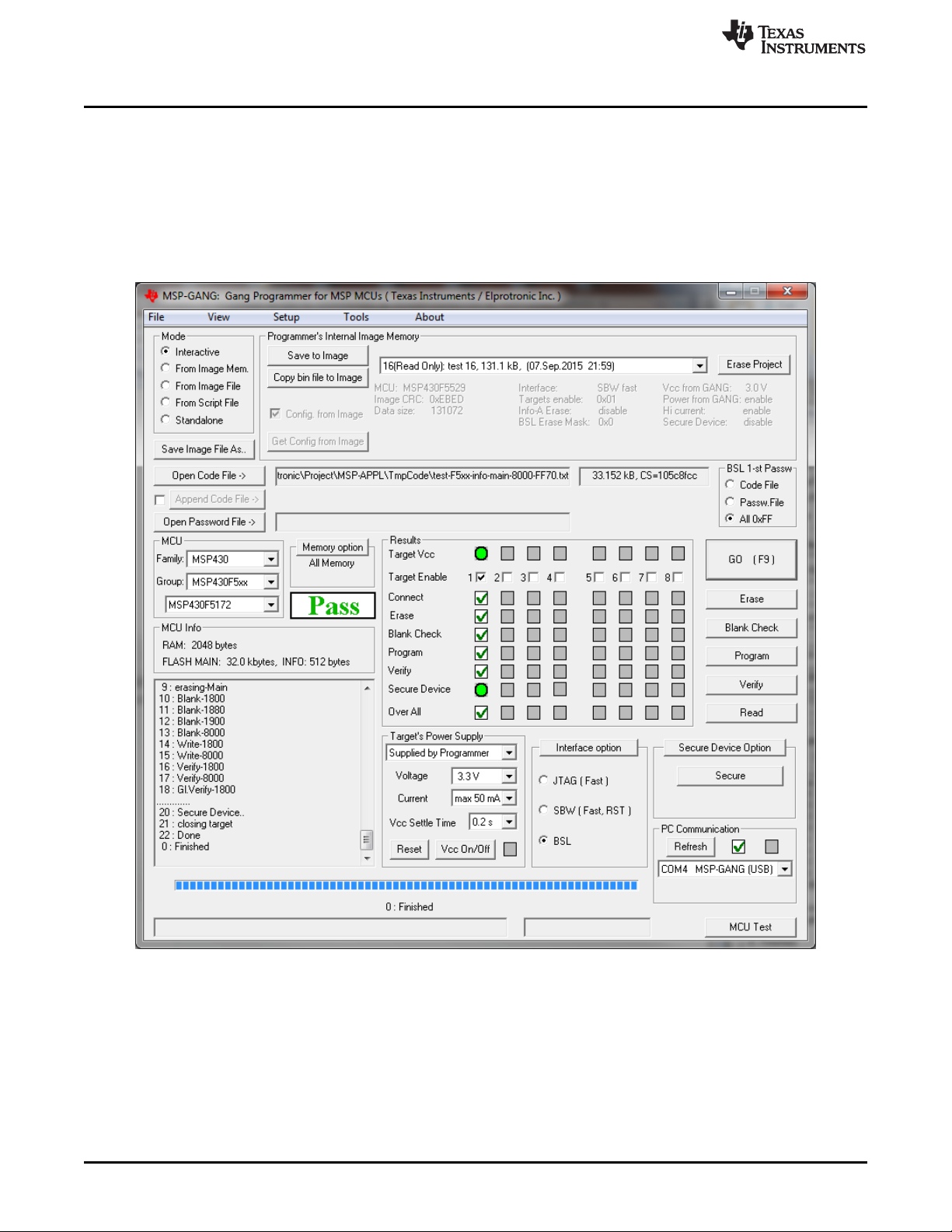
installation. Figure 2-1 shows the MSP Gang Programmer GUI in the Interactive Mode (see the Mode
group in the top left corner). This window is used to select the target microcontroller, code file used for
programming, power supply options, communication interface, and more. This window also shows the
result of programming and any errors, if they occur.
Figure 2-1. Main MSP Gang Programmer Dialog GUI, Interactive Mode
2. Select a target device using the MCU Family, then MCU Group, and then desired MCU Type.
3. Select the code file to be programmed into the devices using the Open Code File button or pulldown
menu: File→Open Code File. The formats supported for the code file are TI (.txt) and Intel (.hex) and
Motorola (.s19, .s28, .s37). Code size and checksum appear on the right side (for details on how the
checksum is calculated, see Section 2.1.13).
4. Optionally add another code file to be programmed into the devices using the Append Code File button
(check the box on the left to enable this option). This feature is useful for updating BSL firmware in 5xx
or 6xx MCUs. The two code files are combined together to create one final code file. If a conflict is

www.ti.com
Programming MSP Flash Devices Using the MSP Gang Programmer
15
SLAU358Q–September 2011–Revised October 2019
Submit Documentation Feedback
Copyright © 2011–2019, Texas Instruments Incorporated
Operation
detected, a warning appears; however, if programming proceeds without changes the second code file
overwrites the conflict area. Code size and checksum appear on the right side.
5. Some MCUs (for example, the MSP430FR57xx) provide a method of disabling JTAG by programming
a password to flash memory. The password should be specified as data to be programmed starting at
0xFF80 and up to 0xFFFF (where 0xFF80 must be 0xAAAA, 0xFF82 must be the size of the password
in words, and 0xFF88-0xFFFF contains the password). The code file must contain password contents
if you intend to lock JTAG using the password feature after programming. If the MCU is already locked
using a previously programmed code file, then you must provide the password section (or entire old
code file) using the Open Password File button if and only if the password section is different.
Functionally, if the MCU is locked by password, the code file’s password section is first used to attempt
to unlock the MCU. If that fails, then the password file’s contents are used to attempt to unlock the
MCU. If both attempts fail, the MCU remains locked and JTAG access fails. Password file contents are
not used to program the MCU.
6. In the Target power group, select the desired V
CC
voltage and select if the target is supplied from the
MSP Gang Programmer or from an external power supply. If targets are supplied by the programmer,
then select the maximum current used by each target, 30 mA or 50 mA.
7. In the Results group, select desired target devices to be programmed. After programming has
concluded, a green checkmark or lights appear for successful operations for each target.
8. In the Interface selector, choose the desired interface (JTAG, SBW, SWD, or BSL) and communication
speed (fast, medium, or slow).
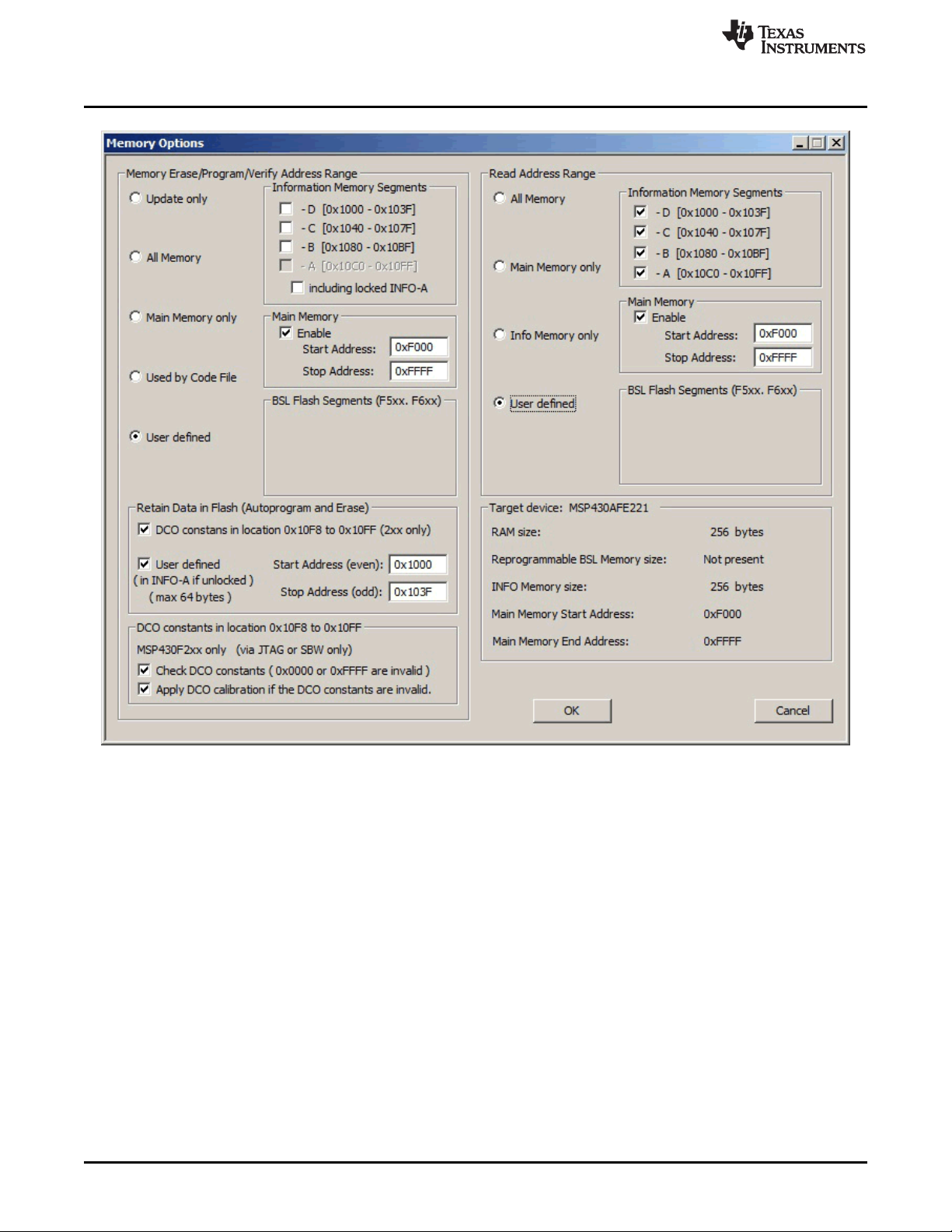
9. In the Memory Options dialog (pulldown menu: Setup→Memory options ) shown in Figure 2-2, select
desired memory space to be programmed. By default, the selected option is All Memory and it is
correct for most programming tasks (Section 2.1.5 describes how to use the memory configuration
window).
Programming MSP Flash Devices Using the MSP Gang Programmer
www.ti.com
16
SLAU358Q–September 2011–Revised October 2019
Submit Documentation Feedback
Copyright © 2011–2019, Texas Instruments Incorporated
Operation
NOTE: The user can select which segments of memory are written to or read from.
Figure 2-2. Memory Options
10. In the Reset Options dialog (pulldown menu: Setup→Device Reset ) shown in Figure 2-3, select the
duration of the reset pulse and the delay after reset. By default it is 10 ms, but other options are
available if required by the hardware.