slau358q.pdf - 第30页
Programming MSP Flash Devices Using the MSP Gang Programmer www.ti.com 30 SLAU358Q – September 2011 – Revised October 2019 Submit Documentation Feedback Copyright © 2011–2019, Texas Instruments Incorporated Operation F_V…

www.ti.com
Programming MSP Flash Devices Using the MSP Gang Programmer
29
SLAU358Q–September 2011–Revised October 2019
Submit Documentation Feedback
Copyright © 2011–2019, Texas Instruments Incorporated
Operation
The following example script executes this sequence of commands:
1. Label START is created.
2. V
CC
from programmer to target device is turned OFF.
3. Message box notifies the user of V
CC
setting and asks for permission to proceed with buttons OK and
CANCEL. The program halts here until a button is pressed.
4. If CANCEL was pressed then GOTO finish label (ends the script).
5. If CANCEL was not pressed (in this case this implies that OK was pressed) then load configuration file
test-A.g430cfg to the MSP Gang Programmer. Configuration file test-A.cfg should be prepared before
running this script using Interactive mode.
6. Message box asks the user to proceed. The program halts until OK is pressed.
7. The MSP Gang Programmer programs the target device using the GO function.
8. Message box asks the user if the test succeeded giving a YES or NO choice.
9. If NO was pressed then GOTO START label (start of script).
10. If NO was not pressed (in this case this implies that YES was pressed) then load configuration file
finalcode.g430cfg to the MSP Gang Programmer.
11. The MSP Gang Programmer programs the target device using the GO function. The new configuration
changes the code file.
12. Script jumps to the beginning using GOTO START. This can be used to wait for the next target device
to be connected.
13. Label finish is created.
14. Script ends.
;=====================================================
; Script file - demo program
;-----------------------------------------------------
>START
F_VCCOFF
MESSAGEBOX OKCANCEL
"VCC if OFF now. Connect the test board."
"When ready press the button:"
" "
"OK - to test the board"
"CANCEL - to exit from program"
IF BUTTONCANCEL GOTO finish
; use file name and FULL PATH or relative path to MSP-Gang.dll file location
F_LOADCFGFILE Examples\Script\test.mspgangproj
MESSAGEBOX OK
"Press OK to download the test program."
F_GO
MESSAGEBOX YESNO
"Press YES when the test finished successfully."
"Press NO when the test failed."
IF BUTTONNO GOTO START
; use file name and FULL PATH or relative path to MSP-Gang.dll file location
F_LOADCFGFILE Examples\Script\finalcode.mspgangproj
F_GO
; wait min 0.5 s before turning Vcc ON again
SLEEP 500
Programming MSP Flash Devices Using the MSP Gang Programmer
www.ti.com
30
SLAU358Q–September 2011–Revised October 2019
Submit Documentation Feedback
Copyright © 2011–2019, Texas Instruments Incorporated
Operation
F_VCCON
SLEEP 10000
GOTO START
>finish
END
;=======================================================
2.1.4 Programming in Standalone Mode
The MSP Gang Programmer supports the Standalone mode of programming target devices. In this mode,
the MSP Gang Programmer can only use images for programming because they contain a complete
configuration and code files necessary for the procedure. If the user has not already created an image
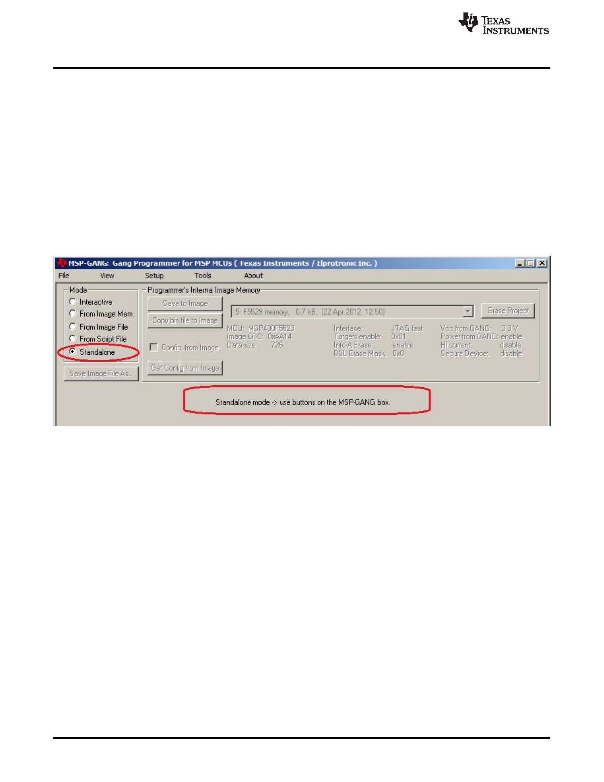
then follow the procedure outlined in Section 2.1.9. When viewed from the GUI, Figure 2-9 shows that all
GUI options are disabled and the MSP Gang Programmer hardware buttons have to be used for
programming.
NOTE: This figure uses the Standalone mode (see the Mode section near the top left corner). All GUI options are
disabled; the MSP Gang Programmer can only be operated using physical controls on the programmer itself.
Standalone mode allows the user to program a target device using an image either from internal memory (up
to 96 different images), or an external SD-Card, without the use of a desktop or laptop computer.
Figure 2-9. Main MSP Gang Programmer Dialog GUI, Standalone Mode
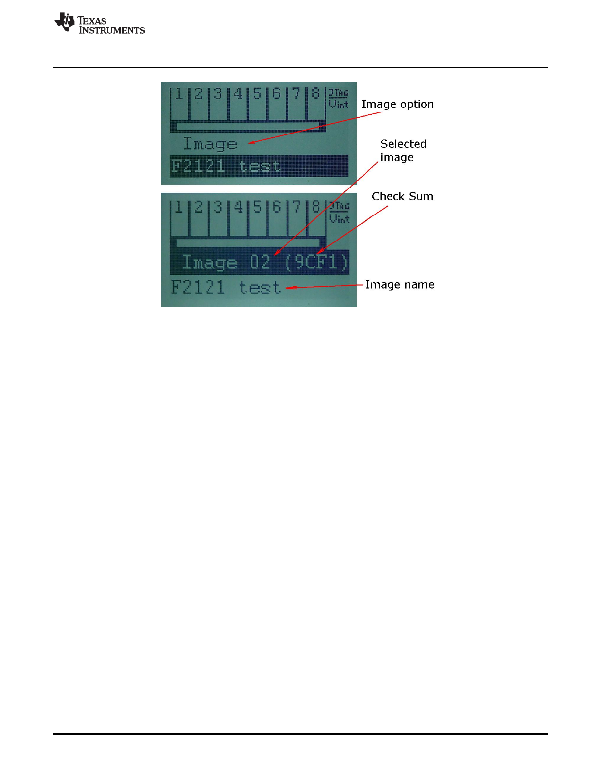
After images have been download to the internal memory or after an SD card with a valid image is
connected to the MSP Gang Programmer, proceed with programming in Standalone mode. Use the arrow
buttons (up and down) and the enter button to select a desired image for programming. A description of
the selected image is displayed on the bottom line, and it is the same description that was created in the
GUI when the Save Image button was pressed (see Figure 2-10).
www.ti.com
Programming MSP Flash Devices Using the MSP Gang Programmer
31
SLAU358Q–September 2011–Revised October 2019
Submit Documentation Feedback
Copyright © 2011–2019, Texas Instruments Incorporated
Operation
Figure 2-10. Image Option
After the desired image has been selected, press the GO button on the MSP Gang Programmer hardware
to start programming. This button operates the same way as the GO button on the GUI. Progress of the
operation in Standalone mode is indicated by a flashing yellow LED and displayed on the LCD display.
The result status is represented by green and red LEDs on the MSP Gang Programmer and details are
displayed on the LCD display. If a green LED is ON only, then all targets have been programmed
successfully. If only the red LED is displaying, that all results failed. If red and green LEDs are on, then
result details should be checked on top of the LCD display. The LCD display shows target numbers 1 to 8
and marks to indicate failure or success: X for failure and V for success. When an error is reported, the
bottom line repeatedly displays an error number followed by a short description with time intervals of
approximately two seconds.
The selected image contains all necessary configuration options and code files required for programming;
however, the user can change the number of target devices being programmed using onboard buttons.
On the main display of the MSP-Gang Programmer (see Figure 2-11), use the up or down arrow buttons
to find the Target En/Dis option. Press the OK button to enter this menu. A sliding cursor appears below
the numbers representing each device at the top of the main display. Use the arrow buttons to underline
the device to enable or disable. Press OK to toggle the devices; press Esc to exit to the main menu. Press
GO to use the selected image to program the selected devices. If another image is selected or the current
image is selected again, the Enable and Disable options reset to what has been configured in the image.