slau358q.pdf - 第46页
Programming MSP Flash Devices Using the MSP Gang Programmer www.ti.com 46 SLAU358Q – September 2011 – Revised October 2019 Submit Documentation Feedback Copyright © 2011–2019, Texas Instruments Incorporated Operation 2.1…
www.ti.com
Programming MSP Flash Devices Using the MSP Gang Programmer
45
SLAU358Q–September 2011–Revised October 2019
Submit Documentation Feedback
Copyright © 2011–2019, Texas Instruments Incorporated
Operation
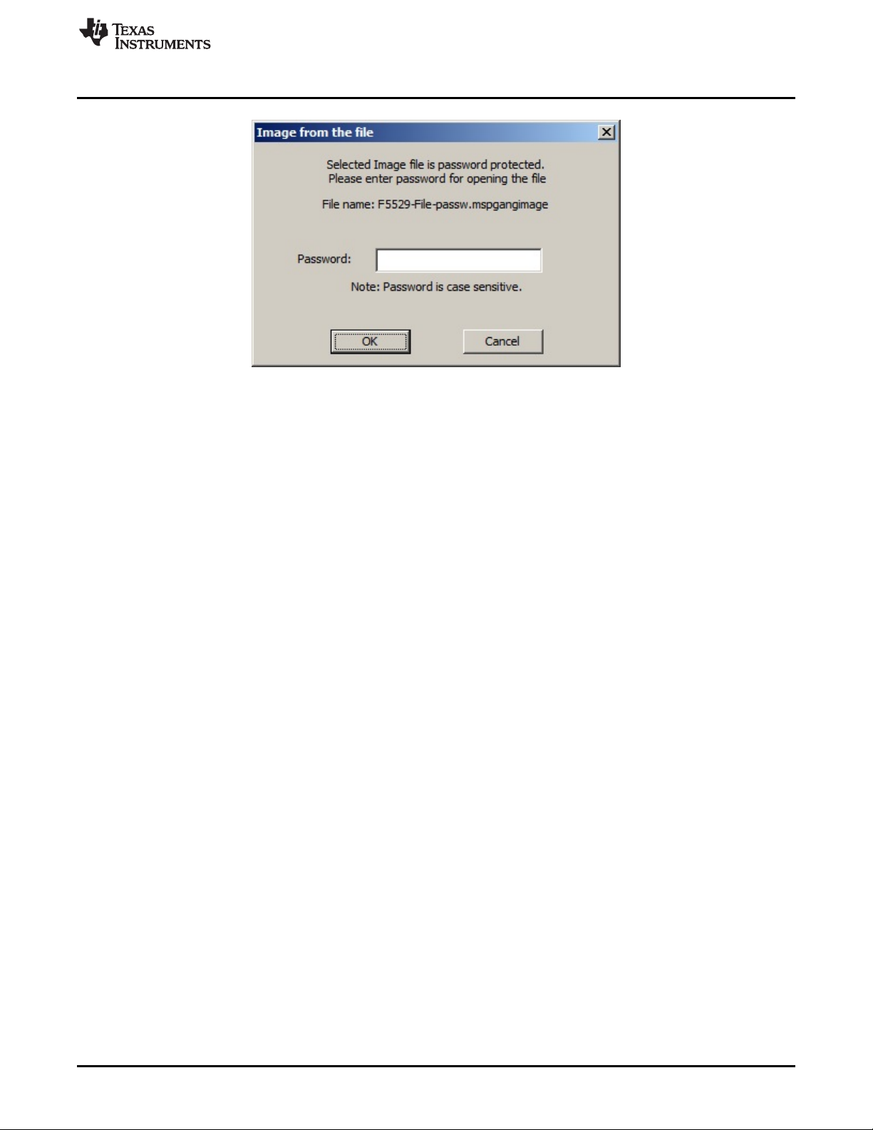
Figure 2-22. Password for Image File
2.1.11 Programming From SD Card
The MSP Gang Programmer can program target devices with an image loaded from an external SD card.
To program from an external SD card, copy a binary file (".mspgangbin") created using steps described in
Section 2.1.9 to the root directory of the SD card (preserve the original extension of ".mspgangbin"). If
multiple binary files are present in the root directory of the SD card, the first one found is used (the first
one found is not necessarily the first one alphabetically). To ensure that the desired binary file is used,
verify that only one binary file with the proper extension .mspgangbin is present in the root directory. The
name of the selected file is displayed on the LCD screen of the MSP Gang Programmer.
When the SD card is connected to the MSP Gang Programmer, internal memory is disabled and an image
can only be read from the SD card. This mechanism has been deliberately implemented to aid in
production because inserting an SD card to the MSP Gang Programmer leaves users with only one option
for programming a target device and, therefore, less possibility for misconfiguration errors.
2.1.12 File Extensions
MSP Gang Programmer software accepts the following file extensions:
Code hex files
*.txt Texas Instruments
*.s19,*.s28,*.s37 Motorola
*.hex Intel
*.a43 Intel hex format with extensions specified by IAR
Image files
*.mspgangbin binary file, used for saving data in SD card
*.mspgangimage image file, can be password protected for distribution
Script files
*.mspgangsf script file
Project configuration files
*.mspgangproj keep all configuration, file names, and data for used project

Programming MSP Flash Devices Using the MSP Gang Programmer
www.ti.com
46
SLAU358Q–September 2011–Revised October 2019
Submit Documentation Feedback
Copyright © 2011–2019, Texas Instruments Incorporated
Operation
2.1.13 Checksum Calculation
The checksum (CS) that is displayed on the side of the code file name is used for internal verification. The
CS is calculated as the 32-bit arithmetic sum of the 16-bit unsigned words in the code file, without
considering the flash memory size or location. If any portion of the code file specifies only one byte
instead of a 16-bit word, the missing byte is defined as 0xFF for the CS calculation.
The following formula is used.
DWORD CS;
DWORD XL, XH;
CS = 0;
for( addr = 0; addr < ADDR_MAX; addr = addr + 2 )
{
if(( valid_code[ addr ] ) || ( valid_code[ addr+1 ]))
{
if( valid_code[ addr ] )
XL = (DWORD) code[ addr ];
else
XL = 0xFF;
if( valid_code[ addr+1 ] )
XH = ((DWORD) code[ addr+1 ])<<8;
else
XH = 0xFF00;
CS = CS + XH + XL;
}
}
As an example, refer to the code file below, which is in the TI hex file (*.txt format).
----------------------------------------
@FC00
F2 40
@FC90
28 02 68 92 DB 3B 38 80 05 00 58
@FFFC
4E F9 B6 FA
q
----------------------------------------
The CS is calculated as shown below:
CS = 0x40F2 + 0x0228 + 0x9268 + 0x3BDB + 0x8038 + 0x0005 + 0xFF58 = 0x000290F2
2.1.14 Commands Combined With the Executable File
Programming executable file can be opened with the following commands:
-prj project file with file name or full path and name.
-sf script file with file name or full path and name.
For example:
MSP-GANG.exe -sf test.mspgangsf
or
MSP-GANG.exe -prj test1.mspgangproj
or
MSP-GANG.exe -prj test1.mspgangproj -sf test.mspgangsf
www.ti.com
Data Viewers
47
SLAU358Q–September 2011–Revised October 2019
Submit Documentation Feedback
Copyright © 2011–2019, Texas Instruments Incorporated
Operation
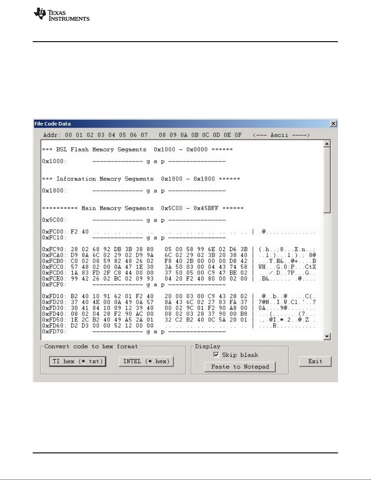
2.2 Data Viewers
Data from code files and from flash memory can be viewed and compared in data viewers. Contents of
the selected file can be viewed by selecting the View→Code File Data option from the drop-down menu.
The Code data viewer, shown in Figure 2-23, displays the code address on the left side, data in hex
format in the central column, the same data in ASCII format in the right column. Data in hex format is
displayed from 0x00 to 0xFF for addresses corresponding to the code file. Data from other addresses is
displayed as double dots (..). If code size exceeds flash memory size in the selected microcontroller, this
warning message is displayed first.
Data out of the Flash Memory Space of the selected MSP.
NOTE: The selected option on the bottom ignores all bytes that have the value of 0xFF , which represents empty
bytes.
Figure 2-23. Code File Data
The contents of the code viewer can be converted to TI (*.txt) or Intel (*.hex) file format by clicking on the
TI hex or INTEL button.