slau358q.pdf - 第67页
www.ti.com Detailed Description of Commands 67 SLAU358Q – September 2011 – Revised October 2019 Submit Documentation Feedback Copyright © 2011–2019, Texas Instruments Incorporated Firmware 3.5.2.2 Boot Commands Disable T…
Command Messages
www.ti.com
66
SLAU358Q–September 2011–Revised October 2019
Submit Documentation Feedback
Copyright © 2011–2019, Texas Instruments Incorporated
Firmware
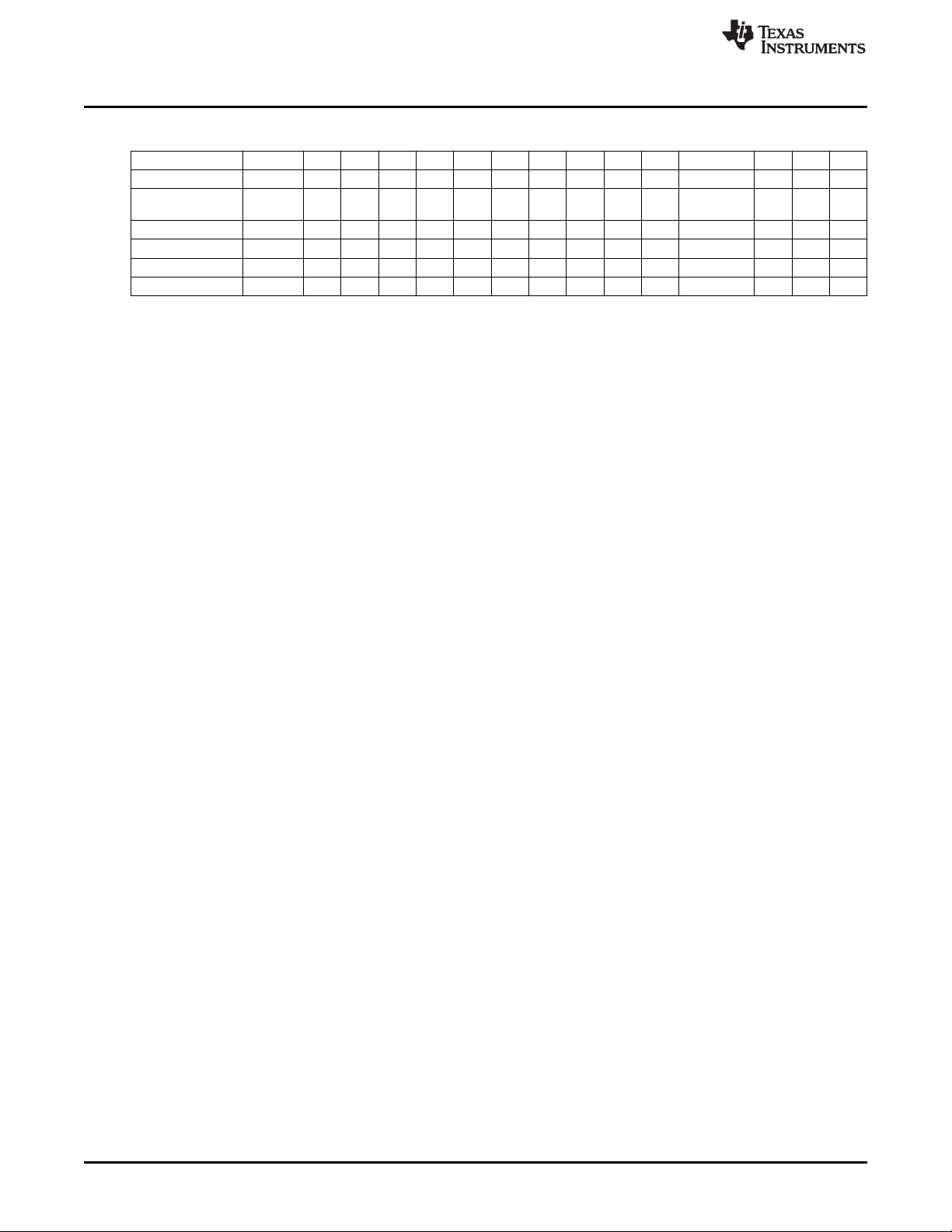
Table 3-1. Data Frame for Firmware Commands
(1) (2)
(continued)
Display Message 3E 54 n+4 n+4 A1 A2 – – n 00 D1 D2...Dn CKL CKH ACK
Set IO State 3E 4E 0C 0C VL VH – – 08 00 D1 D2...D8 CKL CKH ACK
Set Temporary
Configuration
3E 56 06 06 A1 A2 – – 2 0 D1 D2 CKL CKH ACK
Get Gang Status 3E 58 04 04 A1 0 – – 0 0 – – CKL CKH –
Response —,,,--- 80 0 n n D1 D2 D3 D4 D5 D6 D7 D8...Dn CKL CKH
Remote Selftest 3E 71 n+6 n+6 A1 A2 A3 A4 n 0 D1 D2...Dn CKL CKH
Response----,,--- 80 0 n n D1 D2 D3 D4 D5 D6 D7 D8...Dn CKL CKH
3.4.2 Checksum
The 16-bit (2-byte) checksum is calculated over all received or transmitted bytes, B1 to Bn, in the data
frame except the checksum bytes themselves. The checksum is calculated by XORing words (two
consecutive bytes) and bit-wise inverting (∼) the result, as shown in the following formulas.
CHECKSUM = INV [ (B1 + 256 × B2) XOR (B3 + 256 × B4) XOR...XOR ((Bn – 1) + 256 × Bn) ]
or
CKL = INV [ B1 XOR B3 XOR...XOR Bn–1 ]
CKH = INV [ B2 XOR B4 XOR...XOR Bn ]
An example of a frame for the Execute Self Test command with checksum would appear as:
0x3E 0x35 0x06 0x06 0x00 0x00 0x00 0x00 0x00 0x00 0xC7 0xCC
3.5 Detailed Description of Commands
3.5.1 General
After the prompt byte (0x3E) and the command identification byte CMD, the frame length bytes L1 and L2
(which must be equal) hold the number of bytes following L2, excluding the checksum bytes CKL and
CKH. Bytes A1, A2, A3, A4, LL, LH, and D1 to Dn are command specific. However, the checksum bytes
CKL (low byte) and CKH (high byte) are mandatory. If the data frame is received correctly and the
command execution is successful, the acknowledge byte ACK (0x90), in progress byte (0xB0) or received
message with header byte (0x80) as the first one. Incorrectly received data frames, unsuccessful
operations, and commands that are not defined are confirmed with a DATA_NACK = 0xA0.
3.5.2 Commands Supported by the BOOT Loader
3.5.2.1 "Hello" Command
Short TX messages with one byte only
Tx -> 0x0d (CR)
Rx -> 0x90 (ACK)
A response is sent only when the <CR> (0x0D byte) has been detected and when it is not the byte used
as the part of the data frame. This command can be useful for checking communication with the MSP-
GANG. When there is no response, then the baud rate should be changed. After power-up, the USB
interface is used for communication with the MSP GANG; however, the RS-232 receiver is also active. To
reestablish communication between USB and RS-232, the "Hello" command must be sent a minimum of
three times through RS-232. After this, an ACK (0x90) is transmitted through RS-232. This sequence also
works in reverse, to reestablish communication between RS-232 and USB.

www.ti.com
Detailed Description of Commands
67
SLAU358Q–September 2011–Revised October 2019
Submit Documentation Feedback
Copyright © 2011–2019, Texas Instruments Incorporated
Firmware
3.5.2.2 Boot Commands Disable
Tx -> 3E 2A ... ... ... CKL CKH
Rx -> 0x90 (ACK)
Do not use this command. This command is used during firmware or information memory update. Use the
MSP-GANG executable GUI software for updating firmware or information memory update if required.
3.5.2.3 Boot Commands Enable
Tx -> 3E 2B ... ... ... CKL CKH
Rx -> 0x90 (ACK)
Do not use this command. This command is used during firmware or information memory update. Use the
MSP-GANG executable GUI software for updating firmware or information memory update if required.
3.5.2.4 Get Diagnostic Command
The Get Diagnostic command retrieves the result of the preceding gang programming command.
Tx -> 3E 32 04 04 00 00 00 00 CKL CKH
Rx -> 80 00 1E 1E D1 D2 ... D30 CKL CKH
Data bytes D1 to D30 hold the parameters, as follows:
D1-D6: Reserved
D7-D8: Boot revision number: D7 (MSByte), D8 (LSByte)
D9-D10: Hardware version number: D9 (MSByte), D10 (LSByte).
D11 to D12: Firmware version number: D11 (MSByte), D12 (LSByte).
D13 to D20: Character string representing the boot name "G430BOOT"
D21: Comma (,)
D22 to D30: Zero-terminated application firmware name "MSP-GANG"
When the application is modified or is not present, then bits D11-D12 and D22-D30 are modified and can
be used for detection if the application firmware is present, and if present, what type and version of the
application firmware is downloaded.
3.5.2.5 Select Baud Rate Command
Tx -> 3E 38 06 06 BR 00 00 00 00 00 CKL CKH
Rx -> 0x90 (ACK)
The Select Baud Rate command sets the rate of the serial communications. The default is 9600 baud.
Baud rate index 0 to 4, representing the baud rate.
BR → 0 = 9600 baud (default)
BR → 1 = 19200 baud
BR → 2 = 38400 baud
BR → 3 = 57600 baud
BR → 4 = 115200 baud
The Select Baud Rate command takes effect (that is, changes the baud rate) immediately.
3.5.2.6 Erase Firmware Command
Tx -> 3E 39 ... ... ... CKL CKH
Rx -> 0x90 (ACK)
Do not use this command. This command is used during firmware or information memory update. Use the
MSP-GANG executable GUI software for updating firmware or information memory update if required.

Detailed Description of Commands
www.ti.com
68
SLAU358Q–September 2011–Revised October 2019
Submit Documentation Feedback
Copyright © 2011–2019, Texas Instruments Incorporated
Firmware
3.5.2.7 Load Firmware Command
Tx -> 3E 3A ... ... ... CKL CKH
Rx -> 0x90 (ACK)
Do not use this command. This command is used during firmware or information memory update. Use the
MSP-GANG executable GUI software for updating firmware or information memory update if required.
3.5.2.8 Exit from Firmware Update Command
Tx -> 3E 3B ... ... ... CKL CKH
Rx -> 0x90 (ACK)
Do not use this command. This command is used during firmware or information memory update. Use the
MSP-GANG executable GUI software for updating firmware or information memory update if required.
3.5.2.9 Get Label Command
The Get Label command retrieves all hardware and software information.
Tx -> 3E 40 04 04 00 00 00 00 CKL CKH
Rx -> 80 00 8C 8C D1 D2 ... D140 CKL CKH
Data bytes D1 to D140 hold the parameters, as follows:
D1, D2: BOOT software ID ("B430" )
D3-D6: BOOT software version ( 01 00 01 00 )
D7, D8: API software ID ("A430" )
D9-D12: API software version ( 01 00 01 09 )
D13, D14: Boot revision number: D7 (MSByte), D8 (LSByte)
D15, D16: Hardware version number: D9 (MSByte), D10 (LSByte).
D17, D18: Firmware version number: D11 (MSByte), D12 (LSByte).
D19-D26: Character string representing the boot name "G430BOOT"
D27: Comma ','
D28-D36: Zero-terminated application firmware name "MSP-GANG"
D37-D44: MCU's Silicon Unique Number
D45-D76: Zero-terminated string of the Programmer description.
D77-D108: Access keys
D109-D116: Programmers serial number YYMMnnnn
D117-D120: MFG ID "ELP "
D121-D124: Hardware ID "G430"
D125-D126: Hardware revision 0x0101 (rev 1.01)
D127-D140: Spare
3.5.2.10 Get Progress Status
The Get Progress Status command is a low-level command and can be used at any time, even if the
MSP-GANG is busy with other tasks. It replies to the command without interrupting the currently serviced
process. Some commands that have the long execution time requires use the Get Progress Status
command for monitoring the current state. For example, the Main Process command that can be executed
a few seconds or more, responding with character "In Progress 0xB0" as fast as the command has been
received and accepted. The communication link has been released and ready to use the Get Progress
Status command. Now the current status and progress data can be monitored by polling the Get Progress
Status command. Contents of the progress status contains current task number, chunk number, and
information about what tasks have been already finished (erase, blank check, program, verify and more).
Additionally, the comment displayed on the LCD display is also available in the progress status message.
This makes it possible to mirror the progress status on a PC screen and for the status on the PC screen to
appear the same as it is in the MSP-GANG LCD display. The internal firmware the progress status buffer
is always updated when the new task or new chunk is executed. In cases where the LCD is updated
frequently, it might not be possible for the PC screen to exactly mirror it. If polling is done more frequently,