DECAN_S2_Operation(ENG_Ver4.1).pdf - 第47页
It ems t o b e inspe ct e d du r ing p r oduction Chap ter 4 Advanced Chip Shooter DE CAN S2 O pe rat ion H an db ook 4-4 This chapter describes the methods for temporary stop of the machine(Continue / Start mode), emerg…
Items to be inspected during production
Chapter 4
Advanced Chip Shooter
DECAN S2 Operation Handbook
4-3
This chapter describes the methods for temporary stop of the
machine(Continue / Start mode), emergency stop (by manual/ by
system) and the restarting the production after emergency stop when
checking errors or other items and taking measures during production.
Take measures of instantaneous stop > Take measures against defective pickup
Take measures of instantaneous stop
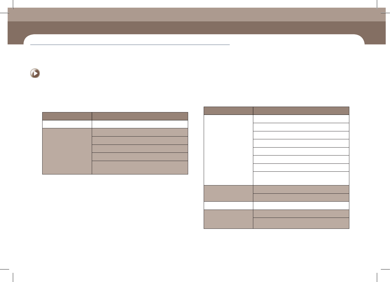
1. Take measures against defective pickup
(check the cause of the defect)
◈Part supply error
Classification of Causes Sub-classification of Causes
Tape installation error Incorrect installation of tape reel in the tape feeder
Part turnover/
edgestanding
Defective reel
The tape guide has been magnetized
Tape guide/Tape guide shutter deformation
Defective tape feeder shutter operation
Defective part feeding speed (odd shaped part
feeder)
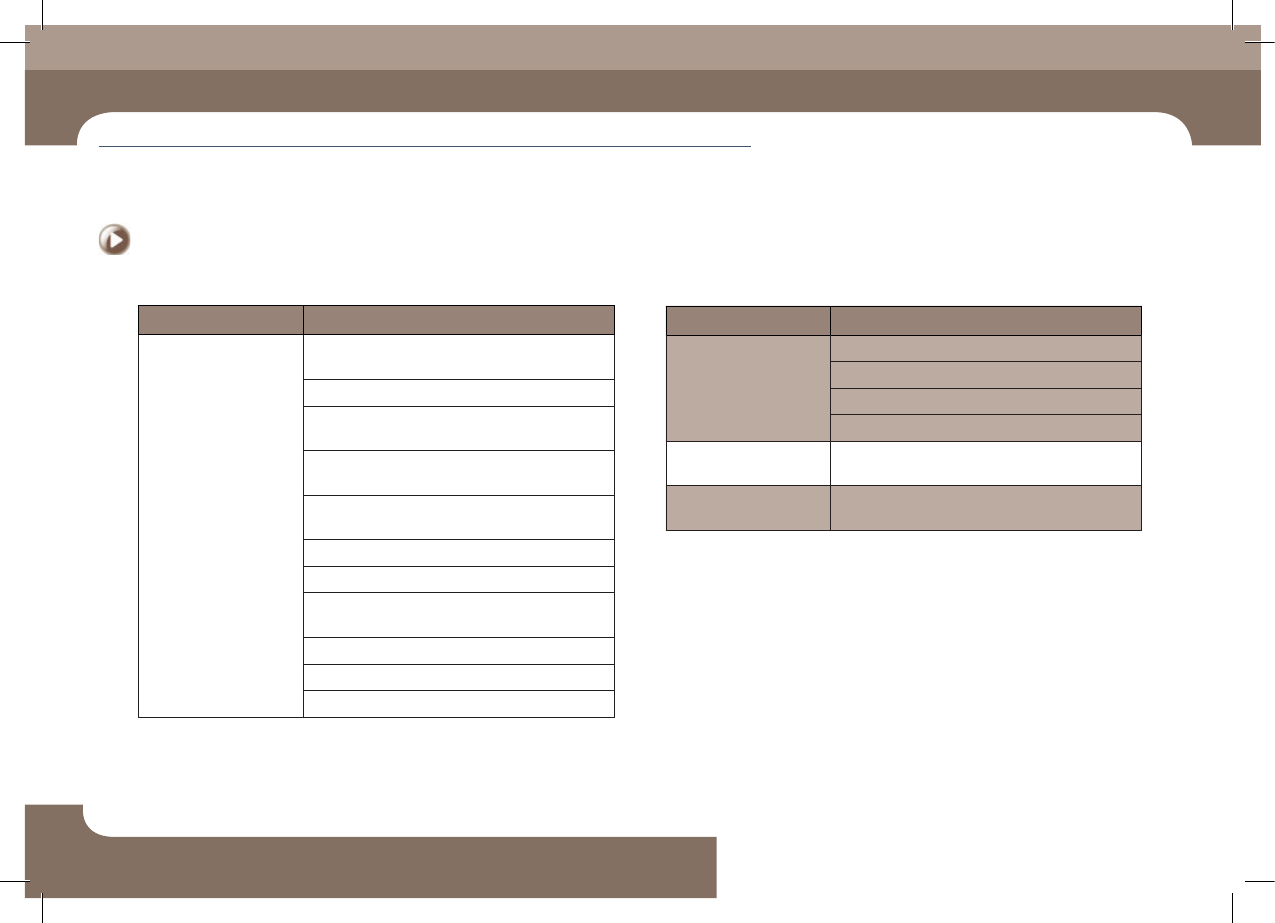
Classification of Causes Sub-classification of Causes
Defective feeding
Insufficient tape feeder maintenance
Defective tape feeder motor operation
Defective tape feeder cylinder operation
Insufficient feeding force of the feeder
Spring damage and separation
Pitch error
Defective index sensor
Part has not been fed due to insufficient vibration of
the vibration feeder
Defective vinyl discharge
The tape vinyl has been curled inside the tape guide
Abnormal vinyl discharge
Tape jamming A part is stuck in the tape discharge path
A part beside the
corresponding part
jumped off
Pickup Z setup error
Fast down movement for pickup
Take measures of instantaneous stop
Items to be inspected during production
Chapter 4
Advanced Chip Shooter
DECAN S2 Operation Handbook
4-4
This chapter describes the methods for temporary stop of the
machine(Continue / Start mode), emergency stop (by manual/ by
system) and the restarting the production after emergency stop when
checking errors or other items and taking measures during production.
Take measures of instantaneous stop > Take measures against defective pickup
Take measures of instantaneous stop
Items to be inspected during production
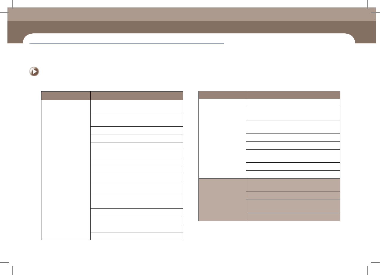
◈Part pickup error
Classification of Causes Sub-classification of Causes
Low vacuum pressure /
delayed vacuum creation
A component of the head's pneumatic system is
defective
Vacuum air line is contaminated
Low vacuum pressure due to an oil leak into the
vacuum generator
Defective contact of the head vacuum solenoid
cable connector
Defective assembly of the solenoid valve connector
in front of the vacuum generator
Defective head I/O board
Defective vacuum sensor board
Air leaks from (Rotary joint, Coil Tube or Fittings,
Vacuum Sensor Board
Main pneumatic pressure setup error
Blow setup error
Incorrect Vac Delay setup
Classification of Causes Sub-classification of Causes
Problem with Nozzle
Standard nozzle not used
Damaged nozzle tip, abnormal nozzle spring tension
Insufficient nozzle maintenance
Use of nozzle unsuitable for the part
A number of odd shaped
materials have dropped
Vacuum check setup error
A part dump error
occurred.
Parts are not dumped properly due to incorrect blow
pressure setup
Items to be inspected during production
Chapter 4
Advanced Chip Shooter
DECAN S2 Operation Handbook
4-5
This chapter describes the methods for temporary stop of the
machine(Continue / Start mode), emergency stop (by manual/ by
system) and the restarting the production after emergency stop when
checking errors or other items and taking measures during production.
Take measures of instantaneous stop > Take measures against defective pickup
Take measures of instantaneous stop
Classification of Causes Sub-classification of Causes
Pickup position Error
Incorrect XY coordinates of the pickup point due to
ball spline deformation
Incorrect setup of the XY coordinates of the pickup
point (Tape, Vibration, Tray Feeder)
Incorrect tape guide position
Splicing error
Incorrect Y position for pickup when installing tape
Incorrectly set X coordinate for pickup when installing tape
Incorrect pickup position adjustment
Incorrect feeder base adjustment
Part wear/distortion in the feeder
Sprocket, ratchet, etc., are contaminated with
foreign materials.
Incorrect setup of the part supply position according
to tray shape and part characteristics
Incorrect setup of Z and Pick Z values
Foreign materials in the feeder base slot and clamp
Incorrect Z offset setup
Z Offset change
◈Part recognition error
Classification of Causes Sub-classification of Causes
Failed to output the
images taken by the
camera
Defective fly camera or fix camera
Defective fly camera I/F cable or defective stage CAM
1 and 2 cables and connections
Defective Fly Camera PW Sync Exit Cable and
connection
Defective vision board
Defective vision I/F board
Defective camera I/O board (total destruction of
internal chips by fire)
Defective power supply
Defective vision board IF cable and connection
Damaged imagen from
the camera Unclear
image from the camera
Defective Fly Cam Sig Ext cable or Fix Cam signal
cable and connection
Defective camera focus
Contaminated camera lens and foreign material on
the lens
Camera dip switch setup error