00192419-02.pdf - 第12页
12 Menu control of the m achine The menu c ontrol an d the user inte rface of th e machine are based on the Microsoft W indows standard. Y ou can initiate a ctions in the individual menus by u sing – function ke ys F1 to…
11
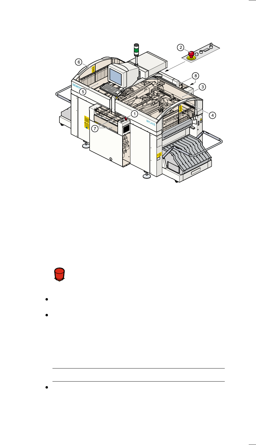
Safety devices
Emergency stop mushroom-head push-buttons
If serious problems occur:
The placement system will stop immediately. Attempt to
eliminate the problem. If this is not possible, call the line
engineer.
Continue processing
Turn the emergency stop mushroom-head push-button to the left to
release it.
Press the Start key.
Protective covers
Make sure that all covers are closed when the machine is operating. As
soon as a cover is opened, the machine will stop and an error message of
the following type may be displayed during placement:
General error: 270 PCB interrupted due to EMERGENCY STOP
Transp.: 1 DEV:1 #E:1
Close the covers and press the Start key.
a Emergency stop mushroom-head push-button, input side
s Emergency stop mushroom-head push-button, output side
d Protective cover, right-hand side
f Protective glass disks, right-hand side
g Protective cover, left-hand side
h Protective glass disks, left-hand side
j Cover and guard on the input belt
k Cover and guard on the output belt
Á
F
12
Menu control of the machine
The menu control and the user interface of the machine are based on the
Microsoft Windows standard. You can initiate actions in the individual
menus by using
– function keys F1 to F12 on the keyboard,
– the trackball and the left-hand mouse button or
– the touchscreen.
– You can open pull-downs and their submenus by pressing the Alt-key in
combination with a ’hot key.
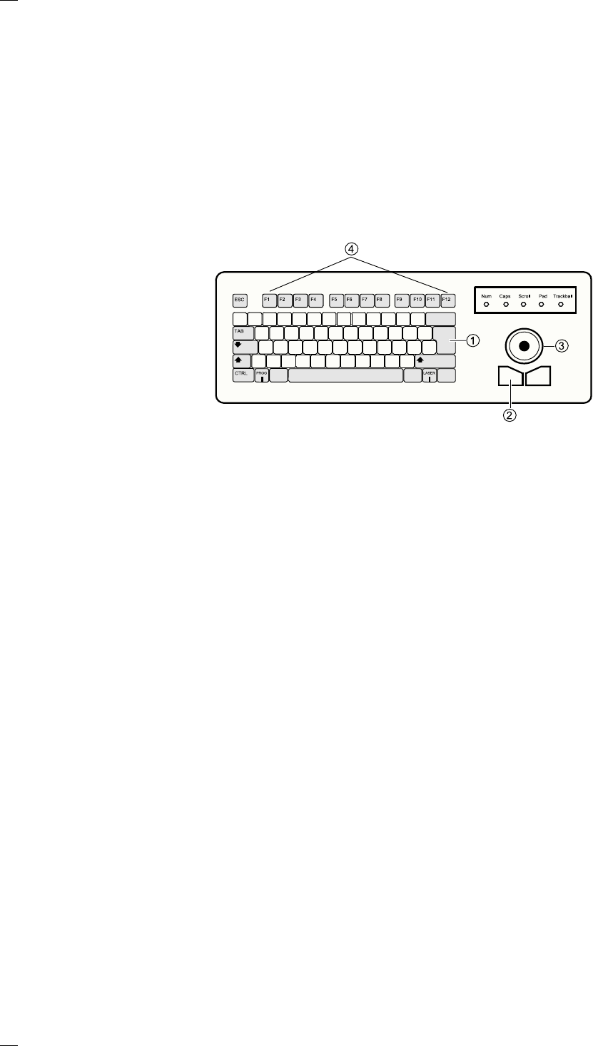
Keyboard with integrated mouse (trackball)
IBM-compatible
keyboard with
German
character set
a Return key
s Left-hand mouse button
d Trackball
f Function keys F1 to F12
Touchscreen
As an alternative to the trackball you can position the mouse pointer on
the screen and operate it by touching the screen with your finger.
13
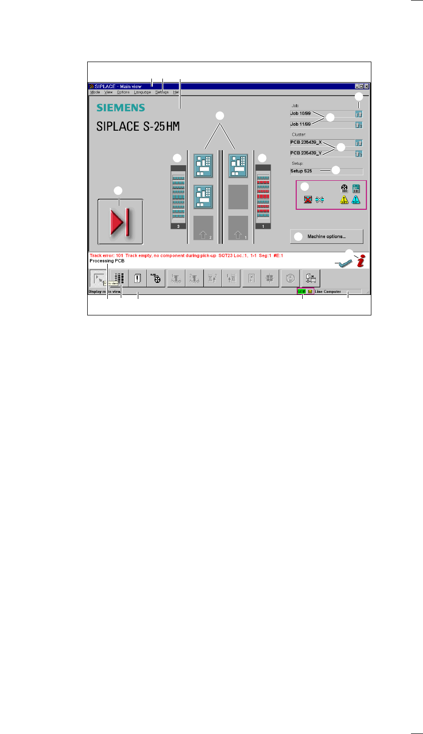
User interface
Main view – arrangement and explanation of the icons
a Title bar showing the currently open menu
s Menu bar with pull-down menus
d Working area / display area
f Button / status display for operator input
g Status box for displaying error messages, statuses and actions required
h Toolbar with icons for the submenus
j Information bar for the menus
k GEM status display
l Display for the machine’s current operating mode
; Troubleshooting status display
A Information and help system
S Button for activating the machine options
D Display for component/PCB barcode, machine / software options, compressed
air cut-out status and connection to the line computer
F Box displaying the currently loaded set-up
G Boxes displaying the clusters loaded for tracks 1 and 2
H Boxes displaying the job names for tracks 1 and 2
J Status display for the transport signal interface:
K Status display for locations 1 - 3
L Status display for the PCB conveyor (transport track 1)
Status display for the PCB conveyor (optional dual conveyor)
Transport track 2
a s d
g hj l
F
G
H
K
L
J
f
k
;
A
S
D
K