00192419-02.pdf - 第15页
15 T oolbar with icons of submenu s (icon h ) NOTES to p oints 6 and 1 0 The single f unctions for Conveyor 2 can on ly be called if a twin convey or has been c onfigured . The GEM i nterface functions can not be c alled…
14
Meaning of the icons
Button / status display for operator input (icon f)
Machine power-up and reference run
When this symbol is displayed, some parts of the user interface cannot be
used. The software is being loaded. Then the status field displays the sta-
tus "Waiting for reference run" and the action "Press start key".
Press the start key. The reference run is then performed.
The machine is ready to perform assembly operations. The following icon
is displayed.
Button / status display for operator input (icon
f)
Stop processing PCB
When you click this icon, the current placement operation is stopped.
Assembly of the PCBs located on the processing conveyors is completed
and they are then transported to the intermediate or output conveyor of
the associated conveyor track. No PCBs are transported into the machine.
Click the icon.
The icon changes to the icon presented below. This continues to be dis-
played until assembly of the current PCBs has been completed and these
have been transported into the intermediate or output conveyor, i.e. until
the processing conveyors have been emptied.
Button / status display for operator input (icon
f)
After "Stop processing PCB" while processing conveyors are emptied
(The triangle in the icon is continuously circled by a small yellow arrow.)
Once the processing areas have been emptied, the following icon is dis-
played.
Button / status display for operator input (icon
f)
Continue processing
This icon is displayed after "Stop processing PCB" or after a machine
stop. (The triangles in the icon move continuously from left to right.)
Click this icon to continue the interrupted operation once the error has
been successfully eliminated.
Click the icon .
Processing is now continued.
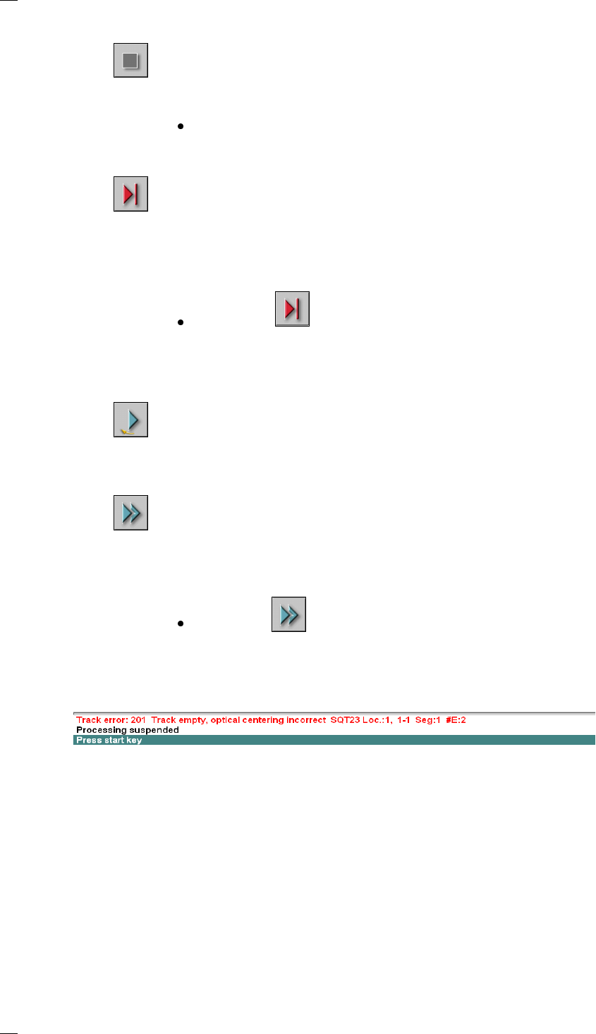
Status box for displaying error messages, statuses and actions
(icon
g)
Line for error information
Lines containing errors that caused machine stoppages have a red
background.
Status display /process status
This line informs the operator about processes running on the machine,
such as ‘Processing suspended’ or ‘Transporting PCB onto output
conveyor’.
Note / action line
Notes to the operator prompting a specific action have a green
background.
15
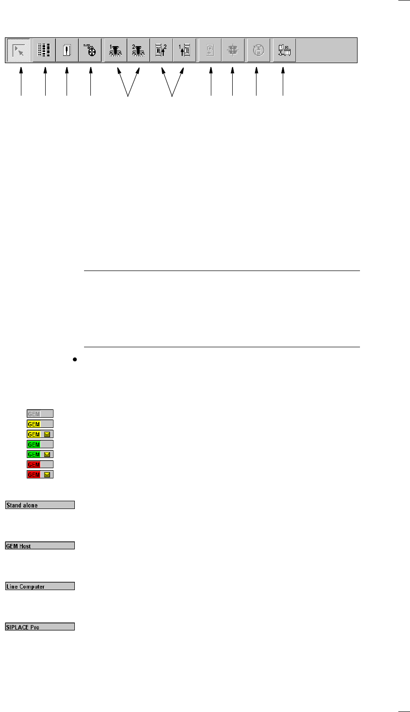
Toolbar with icons of submenus (icon h)
NOTES to points 6 and 10
The single functions for Conveyor 2 can only be called if a twin conveyor
has been configured.
The GEM interface functions cannot be called unless this has been config-
ured.
The "GEM Interface" option cannot be configured in the current software
version.
Click the required button in the toolbar.
The user interface is switched to the corresponding view.
The button corresponding to the view which is currently active itself
becomes inactive.
GEM status display (option) (icon
k)
GEM not initialized
GEM establishing SECS connection, no message from host
GEM establishing SECS connection, message from host
SECS connection online, no message from host
SECS connection online, message from host
SECS connection offline, no message from host
SECS connection offline, message from host
Display for the machine’s current operating mode (icon
l)
Stand alone
The station computer is not connected to an external computer.
Placement programs are loaded from the local hard disk.
GEM Host
The station computer is connected to a host computer. The placement
programs are downloaded from the host computer.
Line Computer
The station computer is connected to the line computer. The placement
programs are downloaded from the line computer.
SIPLACE Pro
In this operating mode, a connection is established with the SIPLACE Pro
programming system.
a Main view
s Set-up, placement functions
d Error, placement functions
f Component feeder, placement functions
g Gantry 1 to 2, single functions
h PCB conveyors 1 and 2 (option), single functions
j Teach fiducials, vision functions
(’Line engineer’ access level or higher only)
k Test component, vision functions
(’Line engineer’ access level or higher only)
l Start SITEST test program (↑ SITEST)
(’Service engineer’ access level or higher only)
; GEM interface (option)
1 8 9 1076432 5
16
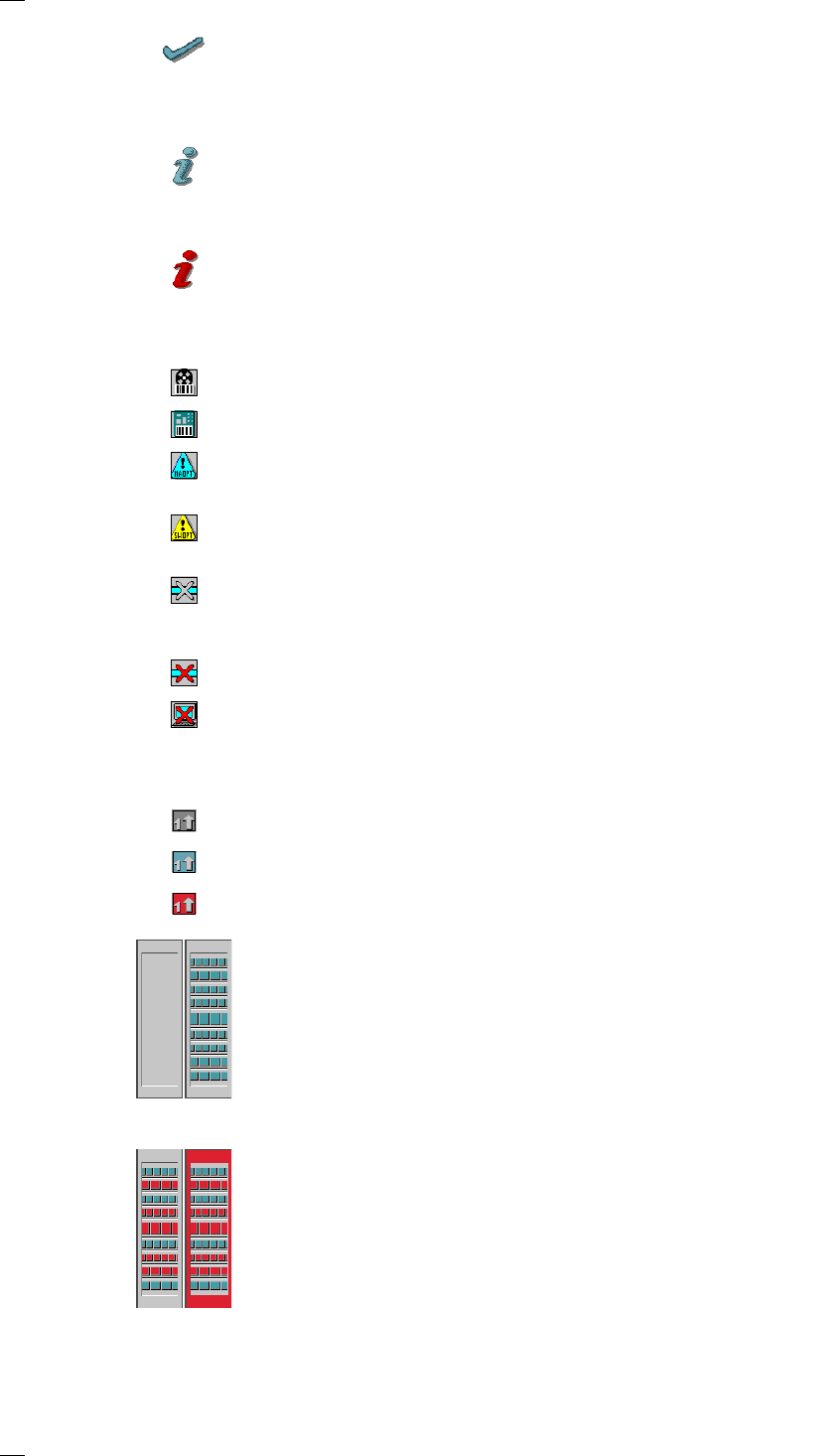
Troubleshooting status display (icon ;)
Click on this icon once you have corrected the fault. The current error in
the status box for displaying error messages
(icon
g) is cleared. The entry is retained in the error lists.
Information and help system (icon A)
Starts the context-sensitive help system for the current view. This contains
brief descriptions of all the controls on screen.
Information and help system (icon
A)
Starts the help system and displays the possible causes of the current
error, together with tips on how to correct it.
Angle for component / PCB barcode … (icon
D)
Barcode-aided replenishment of components is active
The PCB barcode is active.
Machine options were modified (’Line engineer’ access level or higher
only)
Software options were modified (’Service engineer’ access level or higher
only)
The automatic compressed air cut-out is active (’Line engineer’ access
level or higher only). The compressed air supply is disconnected if the
machine has stopped for a predefined period.
The compressed air is switched off.
The connection to the line computer is interrupted. No data can be
received.
Status display for the transport signal interface (icon J)
Grayed out while the machine starts up
Green when the transport signal interface is enabled
Red when the transport signal interface is disabled.
Status display for the locations (icon
K)
a = No set-up at the corresponding location
s = Set-up present
d = Set-up present – at least one "Track empty" error
f = Machine stopped due to several track errors
as
df