00192419-02.pdf - 第17页
17 St atus displ ay for the PCB s (icon L ) PCB being processe d The PCB ha s been taken into the syst em and is being proces sed. The PCB icon is displaye d in blue-gree n. Proces sing of P CB stopped If processin g is …
16
Troubleshooting status display (icon ;)
Click on this icon once you have corrected the fault. The current error in
the status box for displaying error messages
(icon
g) is cleared. The entry is retained in the error lists.
Information and help system (icon A)
Starts the context-sensitive help system for the current view. This contains
brief descriptions of all the controls on screen.
Information and help system (icon
A)
Starts the help system and displays the possible causes of the current
error, together with tips on how to correct it.
Angle for component / PCB barcode … (icon
D)
Barcode-aided replenishment of components is active
The PCB barcode is active.
Machine options were modified (’Line engineer’ access level or higher
only)
Software options were modified (’Service engineer’ access level or higher
only)
The automatic compressed air cut-out is active (’Line engineer’ access
level or higher only). The compressed air supply is disconnected if the
machine has stopped for a predefined period.
The compressed air is switched off.
The connection to the line computer is interrupted. No data can be
received.
Status display for the transport signal interface (icon J)
Grayed out while the machine starts up
Green when the transport signal interface is enabled
Red when the transport signal interface is disabled.
Status display for the locations (icon
K)
a = No set-up at the corresponding location
s = Set-up present
d = Set-up present – at least one "Track empty" error
f = Machine stopped due to several track errors
as
df
17
Status display for the PCBs (icon L)
PCB being processed
The PCB has been taken into the system and is being processed. The
PCB icon is displayed in blue-green.
Processing of PCB stopped
If processing is interrupted by clicking on
"Stop processing PCB",
by a machine stoppage or by pressing the Stop button, the PCB icon
appears in blue-green with contoured edges.
You can continue processing by clicking
or abort it by clicking the PCB icon.
NOTE
The procedure used to abort processing is described below.
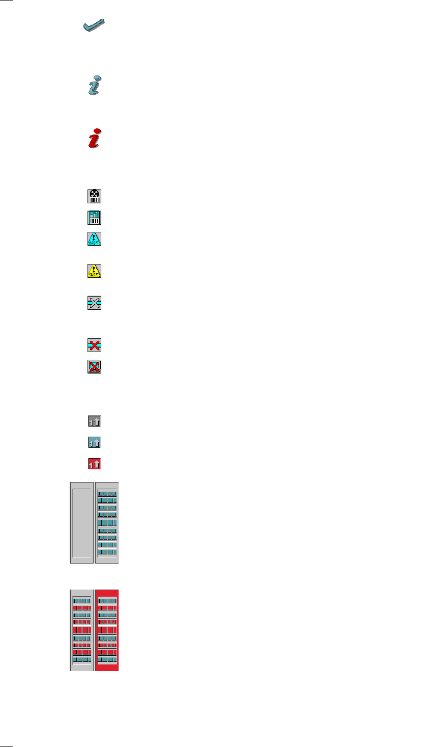
Abort processing PCB
Click the corresponding PCB icon .
If the PCB is located on processing conveyor, the following dialog box is
opened.
Click the checkbox "Abort processing PCB".
Click the Accept button.
Processing of the PCB is aborted.
The incompletely assembled PCB is transported to the output conveyor
and the operator is requested to remove it by hand.
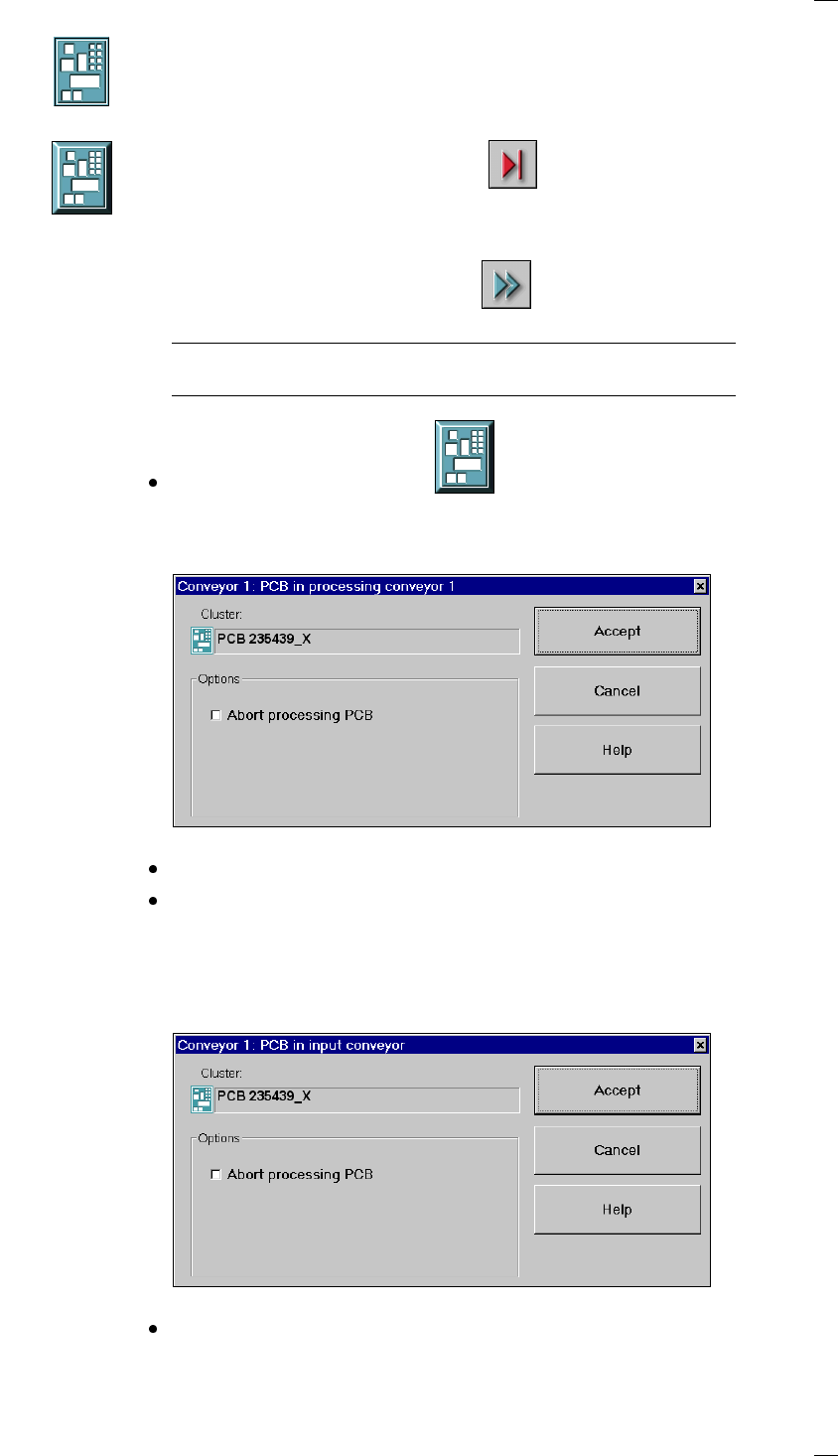
If the PCB is located on the input conveyor, the following dialog box is
opened.
Check the box "Abort processing PCB" if the PCB is to be transported to
the output conveyor without further processing.
18
Click the Accept button.
Processing of the PCB is aborted.
The incompletely assembled PCB is transported to the output conveyor
and the operator is requested to remove it by hand.
Processing of PCB aborted
If processing of the PCB has been aborted by a click on the PCB icon (see
example above), the color of the PCB icon changes to red.
The icon is also displayed in red if a PCB is manually placed on process-
ing conveyor 1 or 2. The PCB is not recognized by the system and is
transported to the output conveyor.
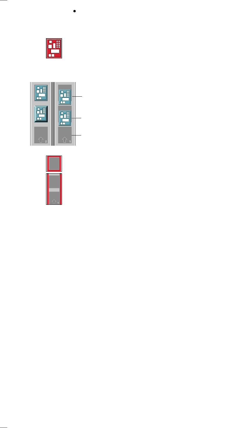
Status display for the PCB conveyor (icon
L)
If a track error, machine error or transport error occurs, the corresponding
graphic is highlighted in red.
If an error occurs in a processing area, the area is displayed with a red
border. Placement of the PCB in this area can be aborted by clicking on
the PCB icon.
If a transport error occurs on a conveyor, the conveyor is highlighted by
a red bar on the right and left.
Output conveyor
The PCB is being transported
Processing conveyor
The PCB is being transported
Input conveyor
The input conveyor is empty