00192419-02.pdf - 第42页
42 PLEASE N OTE Make sure that the nozzle magaz ines are always full. Confirm one Produce th e desired nozzle config uration in the magazin e magazine indicated b y the arro w . T o do this move the cyan bar in the lis t…
41
Click on ‘Confirm one magazine’. The desired and actual values must
tally.
Confirm all Once you have set up the nozzles in every magazine as desired, click on
magazines ‘Confirm all magazines’. The desired and actual values of all magazines
must tally.
‘Segments’ display box
Seg Segment number, up to 12
Actual Displays the nozzle type set up for each segment.
Buttons in the ‘Revolver head’ box
Return all Returns all the nozzles on the revolver head to the appropriate magazine
nozzles of the nozzle changer.
Remove all Throws all the nozzles on the revolver head into the reject bin.
nozzles
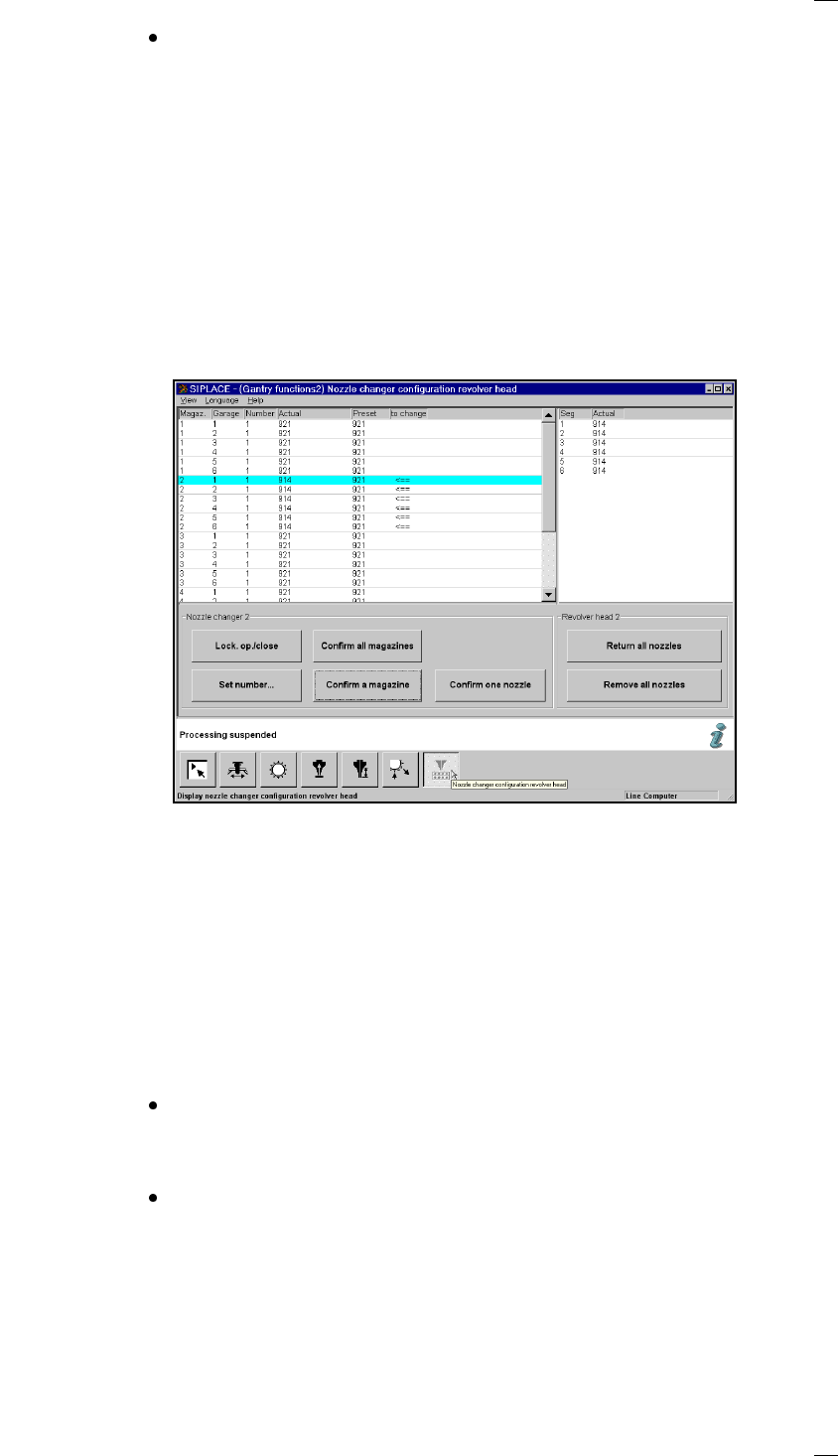
Nozzle changer configuration for the 6-segment revolver head
Display box for the magazines
Magazine: Magazine number, up to 5
Garage Number of garage in the magazine
Number: Number of nozzles in the magazine
Actual: Current set-up in the nozzle changer
Preset: Set-up defined by the line computer
Arrow: If the desired and actual value are different, the difference is indicated by
an arrow.
Buttons in the ‘Nozzle changer’ box
Lock open/closed You can open or close the sliding plate on the selected magazine in order
to fill the nozzle changer magazine manually.
Set number … Click on ‘Set number …’ to open an input box where you can enter the
desired number of nozzles for the magazine.
The magazine on the nozzle changer for the 6-segment revolver head
may contain different nozzles. The different nozzle holders are therefore
shown individually in the display box. Place a nozzle in the holder location
in the magazine. You can add either 0 or 1 nozzle. The default value is 1.
Then click on OK.

42
PLEASE NOTE
Make sure that the nozzle magazines are always full.
Confirm one Produce the desired nozzle configuration in the magazine
magazine indicated by the arrow.
To do this move the cyan bar in the list box to the appropriate line.
Click on ‘Confirm one magazine’. The desired and actual values must
tally.
Confirm all Once you have set up the nozzles in every magazine as desired, click on
magazines ‘Confirm all magazines’. The desired and actual values of all magazines
must tally.
Confirm Set up the nozzle identified with an arrow to the desired status.
one nozzle
To do this move the cyan bar in the display box to the appropriate line.
Click on ‘Confirm one nozzle’. The desired and actual values must tally.
‘Segments’ display box
Seg Segment number, up to 6
Actual Displays the nozzle type set up for each segment.
Buttons in the ‘Revolver head’ box
Return all Returns all the nozzles on the revolver head to the appropriate magazine
nozzles of the nozzle changer.
Remove all Throws all the nozzles on the revolver head into the reject bin.
nozzles
43
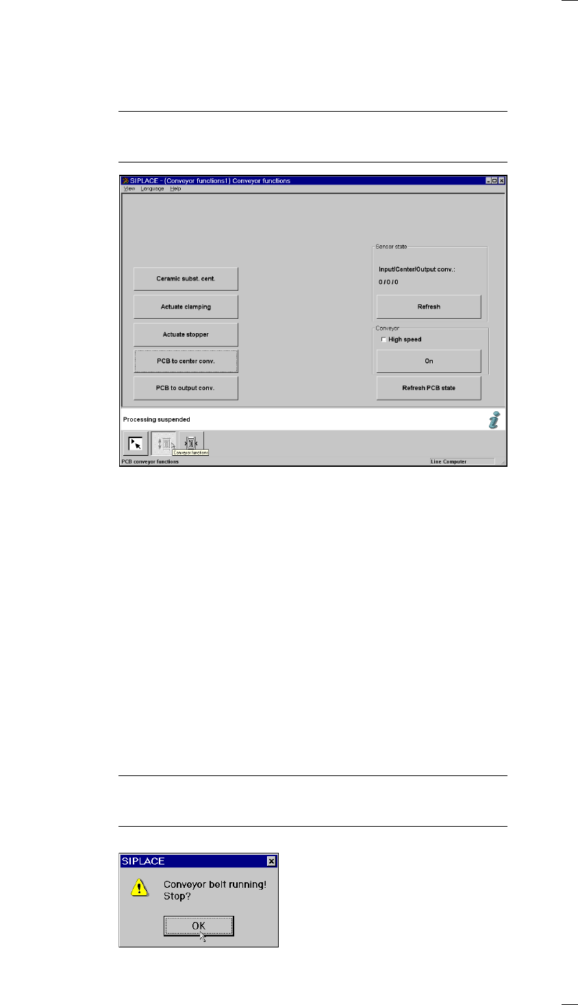
’Single functions PCB transport 1’ menu
This menu is used for checking and setting the function modules of the
PCB conveyor. If the twin conveyor option is installed, the Single functions
PCB transport 2 menu will be activated. The same functions as with PCB
transport 1 will then be available to you.
NOTE
To move the gantries, close the covers and then press the start button. All
gantry and head axes will move at low speed.
Buttons
The next three menu options act in the same way as a toggle switch.
The following menu options act in the same way as a switch (ON/OFF)
when they are clicked.
Ceramic substrate Click on the ’Ceramic substrate centering’ button to activate or
centering (option) deactivate clamping in order to center the substrate.
Actuate clamping Click on the ’Activate clamping’ button to turn clamping on or off.
Actuate stopper Click on the ’Activate stopper’ button to move the stopper in or out.
PCB to center conv. The PCB is transported from input conveyor to the center conveyor, where
it is stopped and clamped in place.
PCB to output conv. The PCB is transported from center conveyor to the output conveyor.
‘Sensor state’ box
Update sensor state (Input/Center/Output conv.) This menu option is used to check the
statuses of the ultrasonic sensors on the input, center or output conveyor:
1 = has responded
0 = has not responded
‘Conveyor’ box
High speed Provides the option of setting different transport speeds.
PLEASE NOTE
Make sure that there are no PCBs on the conveyor belts. The input
conveyor belt only runs at high speed.
On Starts the conveyor belts. The following dialog box appears.