00192419-02.pdf - 第8页
8 Main fault indicator The seque nce of co lors of the ind icator lam p is white (L1 ) - green (L2) - white (L3). It signals different operating statuses and faults on the place- ment syste m. Functional des cription of …
7
Component counter
The component counter shows the number of components that have been
processed.
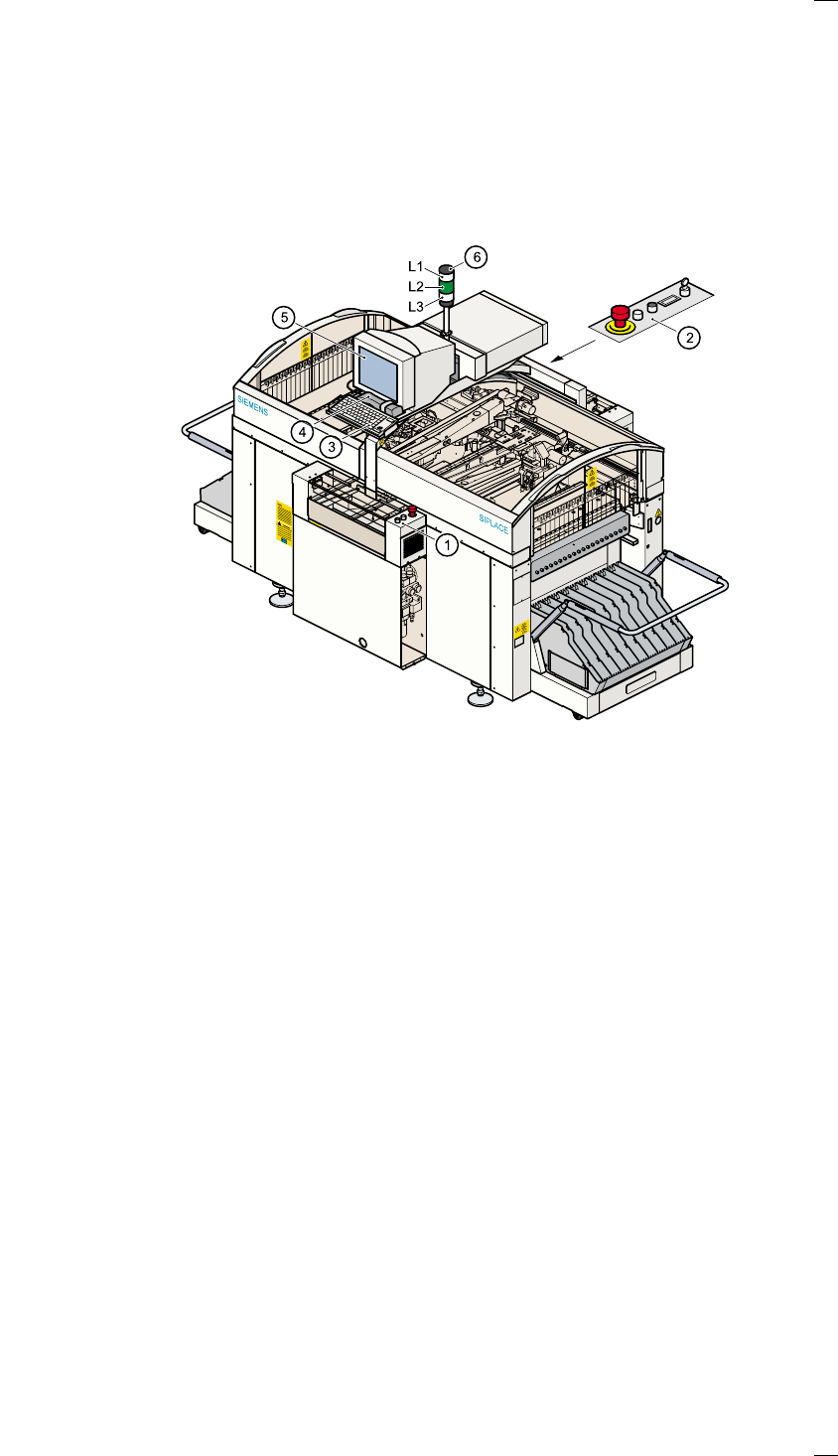
Displays and controls
The following diagram shows the displays and controls.
Description of the displays and controls
All the controls can be reached by anyone who is more than 1.60 m tall.
Touchscreen
As an alternative to the trackball you can position the mouse pointer on
the screen and operate it by touching the screen with your finger. The
resolution is 1024 x 768 pixels.
Keyboard with integral trackball
The keyboard and trackball are located beneath the screen.
Component barcode reader (option)
There is a compartment for a Datalogic DL 910 component barcode
reader between the keyboard and the screen. The barcode reader
enables the components to be set up and topped up quickly and reliably.
a Controls, input side
s Controls, output side
d Keyboard with integral trackball
f Component barcode reader
g Touchscreen
h Main fault indicator
L1 White fault indicator lamp: gantry 2, location 1
L2 Green operating status lamp
L3 White fault indicator lamp: gantry 1, location 3

8
Main fault indicator
The sequence of colors of the indicator lamp is white (L1) - green (L2) -
white (L3). It signals different operating statuses and faults on the place-
ment system.
Functional description of the main fault indicator
Main fault indicator
General operating statuses
– Operating status lamp (green) on continuously
The placement system is in service
– Operating status lamp (green) flashes
The placement system is waiting for a PCB on the input belt or the place-
ment system is waiting until the output belt is free.
– Top white fault indicator lamp L1 flashes
One or more tracks are empty on the right-hand side of the placement
system. The placement system continues to place any remaining compo-
nents.
– Bottom white fault indicator lamp L3 flashes
One or more tracks are empty on the left-hand side of the placement sys-
tem. The placement system continues to place any remaining compo-
nents
– Top white fault indicator lamp (L1) on continuously - green operating sta-
tus lamp (L2) off
An error has occurred on the right-hand side of the placement system ->
the placement system has stopped.
– Bottom white fault indicator lamp (L3) on continuously - green operating
status lamp (L2) off
An error has occurred on the left-hand side of the placement system -> the
placement system has stopped.
– Both white fault indicator lamps (L1 and L3) on continuously - green oper-
ating status lamp off
An error has occurred that affects the entire placement system -> the
placement system has stopped.
Programmed operating status displays
The following table shows the programmed operating status displays in
the standard configuration (version as supplied) and lists their meaning on
the individual lamps of the main fault indicator.
The entries in the table next to "flashes" refer to the frequency with which
the relevant lamp flashes for a given event.
The entry (1, 5), for example, can be explained as follows:
– The first number in the brackets indicates the time, expressed in 100 msec
intervals, for which the fault indicator lamp is switched on,
i.e. 1 x 100 msec in the above example.
L1: Fault indicator lamp (white)
L2: Operating status lamp (green)
L3: Fault indicator lamp (white)

9
– The second number in the brackets indicates the time, expressed in 100
msec intervals, for which the fault indicator lamp is switched off, i.e. 5 x
100 msec in the above example.
L1 (white)
(Top lamp)
L2 (green)
(Middle lamp)
L3 (white)
(Bottom lamp)
Meaning
Status display
flashes (1,10) flashes (7,7) flashes (1,10) Reference run
unchanged flashes (1,5) unchanged Waiting until axes in position
unchanged flashes (7,7) unchanged Waiting for setup data
unchanged flashes (7,7) unchanged Waiting for cluster data
unchanged flashes (7,7) unchanged Load table program
unchanged flashes (7,7) unchanged Position recognition
unchanged flashes (1,10) unchanged Ink spot recognition
unchanged flashes (7,7) unchanged Nozzle configuration test
unchanged flashes (7,7) unchanged Feeder posn. recogn.
unchanged flashes (7,7) unchanged One track is empty
unchanged flashes (7,7) unchanged No further track available
unchanged flashes (7,7) unchanged Go to refill position
unchanged flashes (7,7) unchanged Transport being initialized
unchanged flashes (7,7) unchanged Place PCB in input conveyor
flashes (1,10) flashes (7,7) unchanged
Remove PCB from output con-
veyor
unchanged flashes (7,7) flashes (1,10)
Remove PCB in output conveyor
2
flashes (1,10) flashes (7,7) flashes (1,10) Width adjustment
unchanged flashes (1,10) unchanged Transport PCB
flashes (1,10) flashes (7,7) flashes (1,10)
Both output conveyors are
cleared
on flashes (1,10) on Transport errors
on off on Go to service position
on Placement
flashes (1,20) Waiting for processing data
Error display
on off unchanged Machine error, right
on off unchanged Track empty, right
on off unchanged Nozzle configuration, right
on off unchanged Transport error, right
on off on Fiducial error, left and right
on off on Fiducial error, left and right
unchanged off on Track empty, left
unchanged off on Nozzle configuration, left
unchanged off on Transport error, left
unchanged off on Machine error, left
Pick-up error display
unchanged unchanged flashes (1,20) First track empty, left
unchanged unchanged flashes (5,20) Further tracks empty, left
unchanged unchanged flashes (5,5) Penultimate track in use, left
unchanged unchanged flashes (1,2) Last track in use, left
flashes (1,20) unchanged unchanged First track empty, right
flashes (5,20) unchanged unchanged Further tracks empty, right
flashes (5,5) unchanged unchanged Penultimate track in use, right
flashes (1,2) unchanged unchanged Last track in use, right