00195044-16_UM_VisionTeachStation_DE_EN.pdf - 第119页
Vision Teach Station User Manual 5 Installing the cameras 05/2016 Edition 5.1 Installing stationary cameras, type 25, 33 and 36 119 5.1.1 Connecting cable set 03040355-xx to the camera 5.1.1.1 Opening the camera Place …
5 Installing the cameras Vision Teach Station User Manual
5.1 Installing stationary cameras, type 25, 33 and 36 05/2016 Edition
118
5 Installing the cameras
The vision teach station is supplied with the ordered camera fully installed. The following sections
describe how to install the stationary cameras and the head cameras.
5.1 Installing stationary cameras, type 25, 33 and 36
The type 25, 33 and 36 stationary cameras can be installed on the following placement machines:
Component camera Placement machines
Type 25 (FC camera)
SX series, X-series, D1 and D3
Type 33 (IC camera)
SX series, X-series, D1 and D3
Type 36 (IC camera)
SX series, D1
Tab. 5.1 - 1 Stationary camera for the D and X-series
Installation of the stationary cameras is described with reference to camera type 33. Type 25 and
36 are installed in the same way. Only the coding switch settings are different.
WARNING 5
When you lift or carry the stationary camera, never hold it by the illumination head alone (item 1
in Fig. 5.1 - 1, page 119). The latching connection between the illumination head (item 1) and the
base module (item 2) could be broken by the weight of the base module (item 3 in Fig. 5.1 - 1,
page 119), causing the base module to fall off.
CAUTION 5
The plug-in illumination head (item 1 in Fig. 5.1 - 1) incorporates the illumination section that is
matched to the camera's CCD sensor. You should therefore never swap the illumination heads
between cameras. If you do, the cameras will no longer work.
Vision Teach Station User Manual 5 Installing the cameras
05/2016 Edition 5.1 Installing stationary cameras, type 25, 33 and 36
119
5.1.1 Connecting cable set 03040355-xx to the camera
5.1.1.1 Opening the camera
Place the camera with the base plate (item 4) on a flat, clean surface.
Pull the illumination head (item 1) forward 30 mm or so.
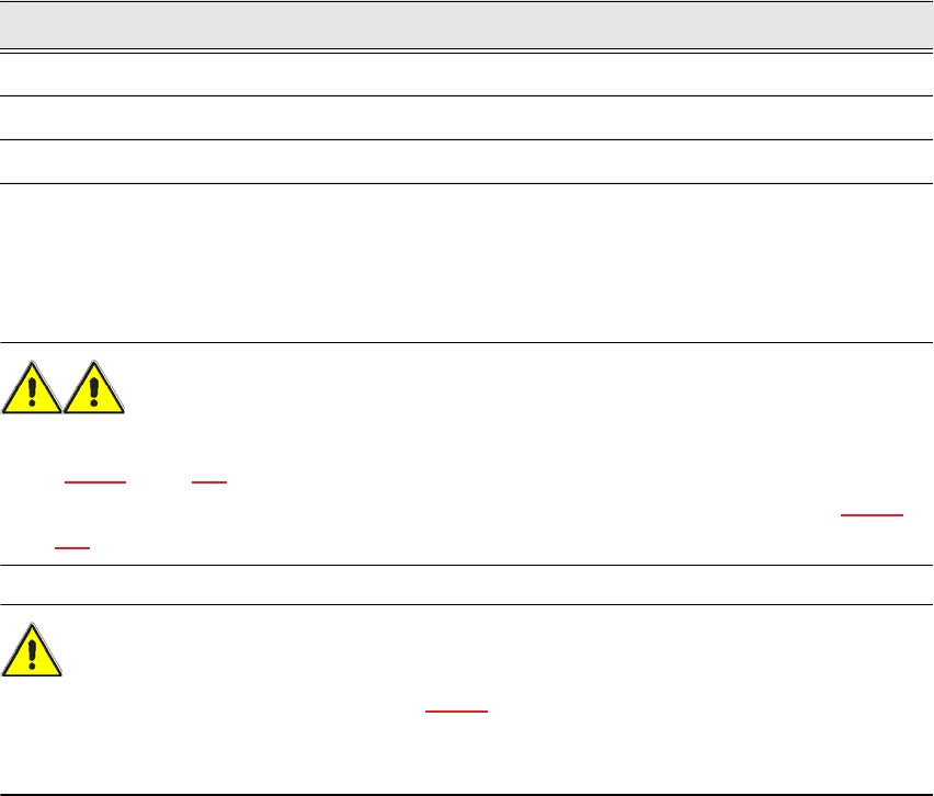
Lift and remove the cover (item 2) from the base module (item 3).
The plug-in connectors and DIP switches are now accessible.
5
Fig. 5.1 - 1 Opening camera type 33
(1) Illumination head
(2) Cover
(3) Base module
(4) Base plate
5.1.1.2 Connecting the cables and checking the DIP switches
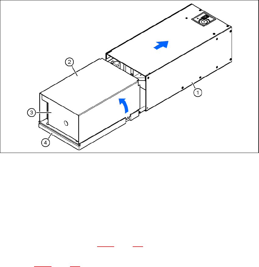
Connect connector X4 on the cable 03040355-W1 to connector X4 on the board. This supplies
the camera with power (see Fig. 5.1 - 2, page 120).
Connect connector X10 on the cable 03040355-W2 to connector X10 on the board (CAN bus)
(see Fig. 5.1 - 2, page 120).
03040355-W2
X12
03040355-W1
(1)
(2)
X4
X10
X5
5 Installing the cameras Vision Teach Station User Manual
5.1 Installing stationary cameras, type 25, 33 and 36 05/2016 Edition
120
5
Fig. 5.1 - 2 Connecting cable set 03040355-xx
(1) DIP switches for camera type and location address
(2) Camera connector for camera cable direct to the PC (see Fig. 4.3 - 2, no. 1, page 117)
X4, X5 power supply connection, connected in parallel
X10 CAN bus connection
NOTE 5
Fit the camera to the base module before you connect the camera bus cable.
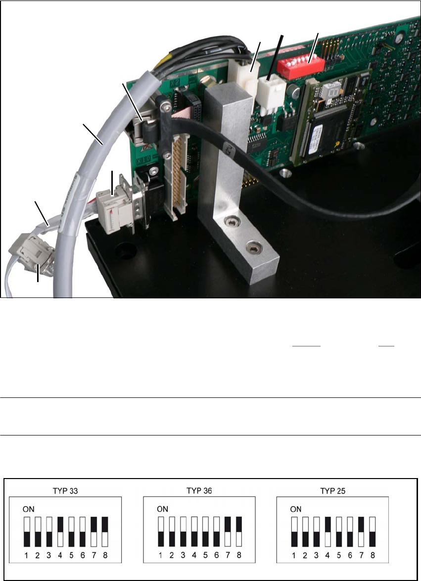
Check the DIP switch settings on the cameras.
Fig. 5.1 - 3 DIP switch settings on the stationary cameras for the vision teach station (version with 8 switches)