OperationInstruction_Vsision XP - 第114页
Page 106 V ISION XP+ V AC 5 Software 5.5 The Masks Menu Operating Instructions V ersion 1.5 5.5.2 Heater - V alue Settings Fig. 5-4 0 Hea ter - V alue Settings Setpoints can be entered a nd actual value s can be di splay…
VISION XP+ VAC Page 105
5 Software
5.5 The Masks Menu
Operating Instructions
Version 1.5
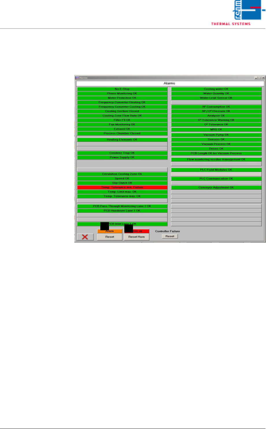
5.5.1 Alarms
Errors and malfunctions are displayed in red here.
Fig. 5-39 Software Window with Alarm Messages
A) Button for switching the horn off. This is the same function which appears
in the main window.
B) Horn Switch
The horn sounds to indicate alarm messages which this switch is turned
on. If, on the other hand, the switch is turned off, alarm messages appear
at the display only. the horn does not sound.
A
B
Page 106 VISION XP+ VAC
5 Software
5.5 The Masks Menu
Operating Instructions
Version 1.5
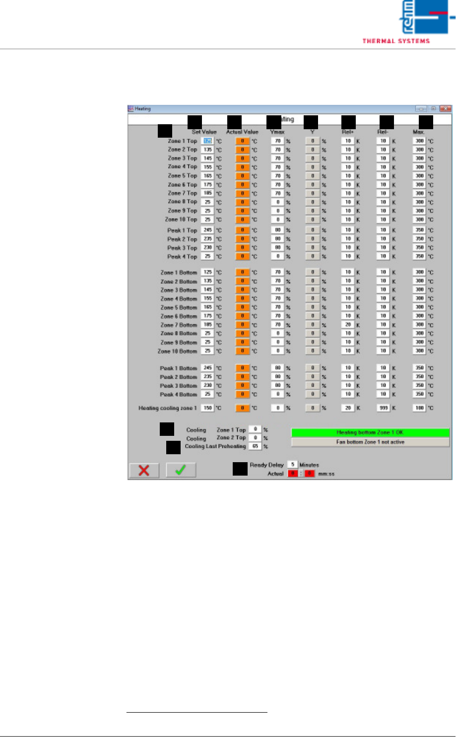
5.5.2 Heater - Value Settings
Fig. 5-40 Heater - Value Settings
Setpoints can be entered and actual values can be displayed in this window.
In addition to this, tolerances and limits for manipulated variables can be
specified here for the heaters.
A) Designations of the individual heaters
B) Setpoint
Entry field for temperature setpoints.
1
These fields are identical to those
in the main window.
C) Actual Value
Temperature display for the heaters.
1
These fields are identical to those
in the main window.
D) Ymax (setpoint limiting)
Maximum heating power as a percentage: If set to less than 100%, heat-
ing power is pulsed in order to limit power.
1. See also page 80, “Use of Color” and “Entering Values”.
FE G HB
A
C D
I
J
K

VISION XP+ VAC Page 107
5 Software
5.5 The Masks Menu
Operating Instructions
Version 1.5
E) Y (current setpoint)
Current manipulated variable
F) Rel+
The relative upper tolerance limit can be selected here, relative to the set-
point. If the tolerance is exceeded, the “Maximum Temperature Tolerance
Exceeded” alarm is triggered.
G) Rel-
The relative lower tolerance limit can be selected here, relative to the set-
point. If the tolerance is fallen short of, the “Minimum Temperature Toler-
ance Fallen Sort Of” alarm is triggered.
H) Max
Maximum permissible temperature can be selected here. If the specified
temperature is exceeded, the “Upper Temperature Limit Value” alarm is
triggered and the heaters are switched off.
I) Cooling in the last preheating zone
In order to prevent overheating of the last preheating zone, cooling can
be adjusted at the top of the last preheating zone by means of an actuat-
ing drive.
Cooling is activated when the actual value 2°C exceeds the setpoint in
this zone. It is deactivated when the “minimal tolerance violation” mes-
sage is generated for this zone.
Cooling should only be activated when actually required. If cooling is re-
quired, the setpoint must be adjusted to the smallest possible value. Av-
erage manipulated value Y for the top of the last preheating zone should
then be roughly 10%.
J) Cooling the preheating zones (SSP+)
The actuator is opened to a preset value. The SSP blower does not
switch on. Additional cooling of the preheating zones is provided by the
building’s extraction system.
K) Delay On
A delay time can be entered here which must elapse before the system
becomes ready for operation after a temperature tolerance has been
reached.
The propagation delay time is indicated in three states, which present the
following time domains.
red - as long as there is a tolerance breach
orange - as long as the propagation delay time is running
green - when the time is expired