OperationInstruction_Vsision XP - 第117页
V ISION XP+ V AC Page 109 5 Software 5.5 The Masks Menu Operating Instructions V ersion 1.5 E) Rel- The relative lower tol erance limit can be s elected he re, relative to the set- point. If the tolerance is fallen short…
Page 108 VISION XP+ VAC
5 Software
5.5 The Masks Menu
Operating Instructions
Version 1.5
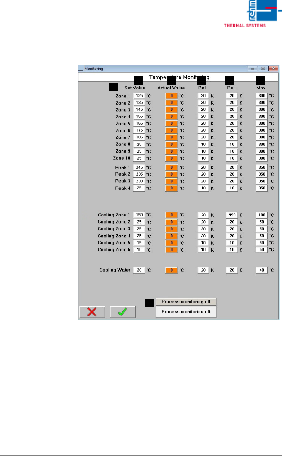
5.5.3 Watchdog – Temperature Monitoring
Fig. 5-41 Watchdog – Temperature Monitoring
Set values and the tolerances for individual temperature supervision are
stated in this window.
A) Designations of the individual process chamber zones
B) Setpoint
The setpoint for internal temperature monitoring is specified.
C) Actual Value
These fields are identical to the display fields in the main window.
D) Rel+
The relative upper tolerance limit can be selected here, relative to the set-
point. If the tolerance is exceeded, the “Maximum Temperature Tolerance
Exceeded” alarm is triggered.
F
E
B
A
C D
G
.
VISION XP+ VAC Page 109
5 Software
5.5 The Masks Menu
Operating Instructions
Version 1.5
E) Rel-
The relative lower tolerance limit can be selected here, relative to the set-
point. If the tolerance is fallen short of, the “Minimum Temperature Toler-
ance Fallen Sort Of” alarm is triggered.
F) Max
Maximum permissible temperature can be selected here.
If the specified temperature is exceeded, the “Upper Temperature Limit
Value” alarm is triggered and the heaters are switched off.
G) CCS Button (optional)
This button is used to switch the Capability Control System on and off.
Page 110 VISION XP+ VAC
5 Software
5.5 The Masks Menu
Operating Instructions
Version 1.5
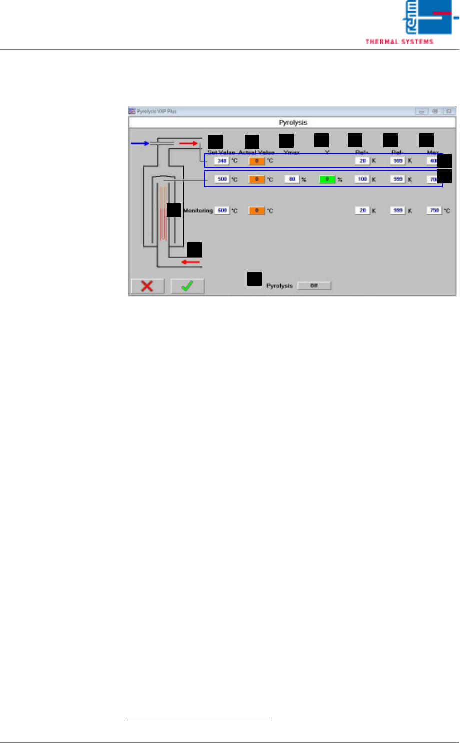
5.5.4 Pyrolysis - Value Settings VXP+
Fig. 5-42 Pyrolysis - Value Settings
Setpoints can be entered and actual values can be displayed in this window.
In addition to this, tolerances and limits for manipulated variables can be
specified here for the heaters.
A) Designations of the individual heaters
B) Setpoint
Entry field for temperature setpoints.
1
These fields are identical to those
in the main window.
C) Actual Value
Temperature display for the heaters.
1
These fields are identical to those
in the main window.
D) Ymax (setpoint limiting)
Maximum heating power as a percentage: If set to less than 100%, heat-
ing power is pulsed in order to limit power.
E) Y (current setpoint)
Current manipulated variable
F) Rel+
The relative upper tolerance limit can be selected here, relative to the set-
point. If the tolerance is exceeded, the “Maximum Temperature Tolerance
Exceeded” alarm is triggered.
G) Rel-
The relative lower tolerance limit can be selected here, relative to the set-
point. If the tolerance is fallen short of, the “Minimum Temperature Toler-
ance Fallen Sort Of” alarm is triggered.
H) Max
Maximum permissible temperature can be selected here.
If the specified temperature is exceeded, the “Upper Temperature Limit
Value” alarm is triggered and the heaters are switched off.
1. See also page 80, “Use of Color” and “Entering Values”.
FE
B C
D
A
G H
I
J
L
K