OperationInstruction_Vsision XP - 第121页
V ISION XP+ V AC Page 1 13 5 Software 5.5 The Masks Menu Operating Instructions V ersion 1.5 K) Status display o f the limit switches The failure „time o ut actual value“ The f ailure „ti me out ac tual value“ t riggers …
Page 112 VISION XP+ VAC
5 Software
5.5 The Masks Menu
Operating Instructions
Version 1.5
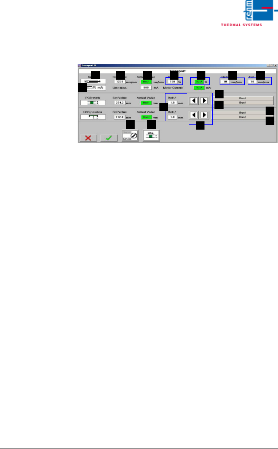
5.5.5 Conveyor Values
Fig. 5-43 Conveyor Values
Setpoints can be entered here, and actual values can be displayed for the
conveyor. In addition to this, tolerances and limits for manipulated variables
can be specified for the conveyor.
A) Designations of the individual functions
B) Setpoint
These fields are identical TO the entry fields in the Main Window, page
87.
C) Actual value
These fields are identical TO the display fields in the Main Window, page
87.
D) Ymax (setpoint limiting)
The maximum speed at which the drive unit is operated is puted in here
as a percentage.
E) Y (current setpoint)
The momentary manipulated variable is displayed.
F) Rel+
The relative upper tolerance limit can be changed here. If these values
are exceeded, the alarm message “Speed“ is generated.
G) Rel-
The relative lower tolerance limit can be changed here. If these values
are fallen short of, the alarm message “Speed“ is generated.
H) Rel+/-
The relative tolerance limit can be changed here. If it is exceeded or fall-
en short of, the system is not ready for operation.
I) Buttons for Adjusting Conveyor Width
For details refer to the Main Window, page 87.
J) Status display for the conveyor unit (= axis)
B
A
C D E F G
H
I
K
J
J
K
ML
N

VISION XP+ VAC Page 113
5 Software
5.5 The Masks Menu
Operating Instructions
Version 1.5
K) Status display of the limit switches
The failure „time out actual value“
The failure „time out actual value“ triggers off the alarm „transport adjust-
ment failure“ and can be reset over Alarm Reset
If the transport cannot be still moved automatically, please check the
transport mechanism. If automatic conveyor operation still isn't possible,
the conveyor system's mechanical components must be inspected.
L) Modes of operation
This field is identical with the field in the main screen.
M) Transport adjustment
This field is identical with the field in the main screen.
N) Conveyor drive current (option)
Momentary current values for the conveyor drive can be monitored here.
An alarm is triggered as soon as the setpoint is exceeded.
Page 114 VISION XP+ VAC
5 Software
5.5 The Masks Menu
Operating Instructions
Version 1.5
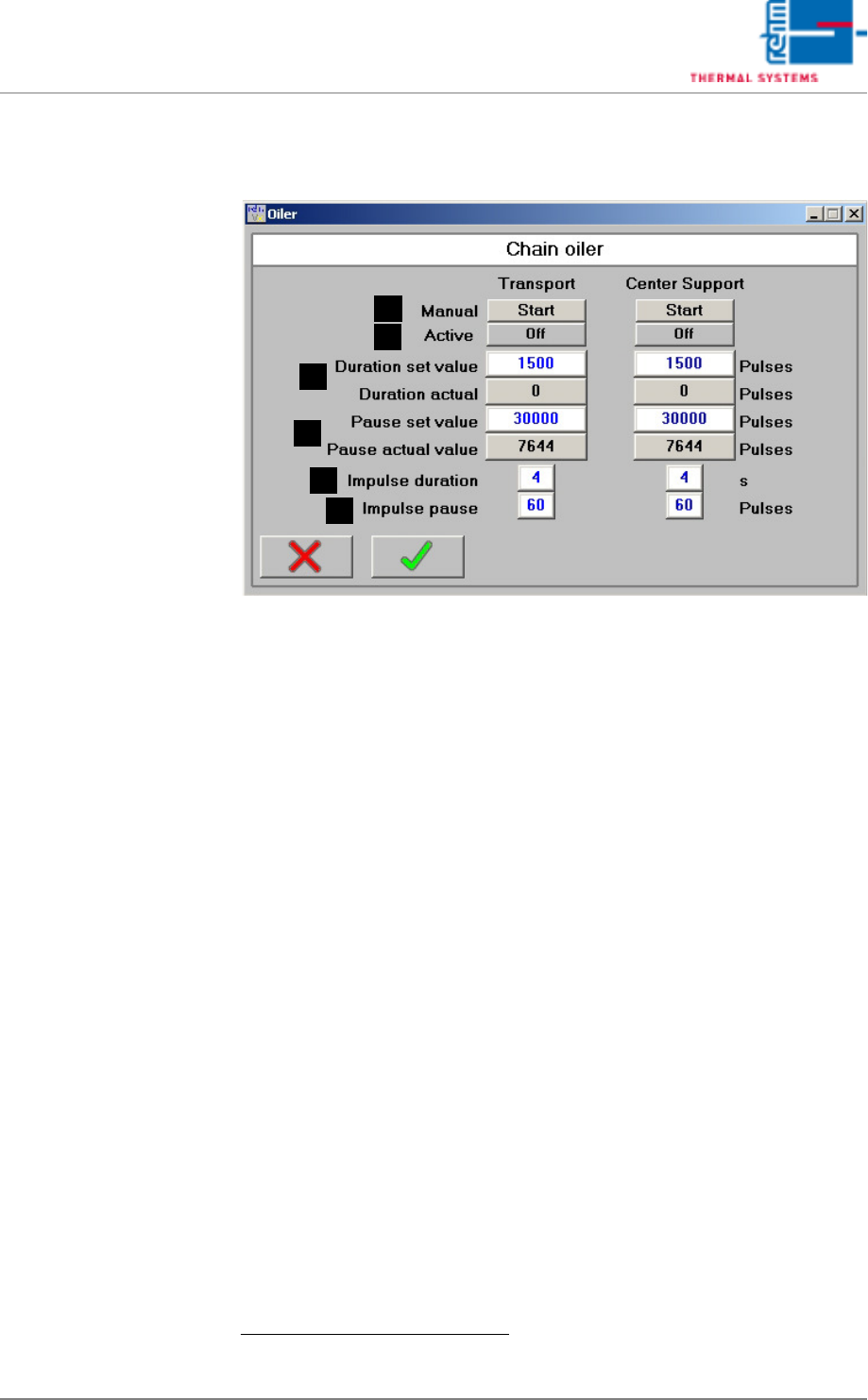
5.5.6 The Chain Lubricator
Fig. 5-44 The Chain Lubricator
The Chain Lubricator window is a virtual timer switch for intervallic control
of the chain lubricator. Chain lubricating intervals and on-time in pulses can
be selected here for the chain lubricating process based upon conveyor belt
pulses generated by the sensor at the drive sprocket.
If the electric magnet is de-energized (interpulse period valve), the pump
pistons are brought into the initial position over spring force and they suck
the chain oil for the next ejection.
A) Start Button
When the chain lubricator is in the pause mode, the chain lubricator is
started manual for the number of pulses specified under duration, after
which pause time is restarted.
B) Status Display
The current status of the chain lubricator is displayed (off or on).
C) Duration
The duration of the active phase is entered to the white field.
1
Duration is
entered in terms of belt pulses.
When the chain lubricator is active, the number of elapsed belt pulses is
displayed in the gray field. During the active phase, the pulse chain lu-
bricator valve function is activated
D) Pause
The duration of the pause between active phases is entered to the white
field. Duration is entered in terms of belt pulses.
1
When the chain lubricator is inactive, the number of elapsed belt pulses
is displayed in the gray field.
1. You can read up on the standard values in the service instructions in the chapter „setting
instructions“.
D
C
B
A
E
F