OperationInstruction_Vsision XP - 第123页
V ISION XP+ V AC Page 1 15 5 Software 5.5 The Masks Menu Operating Instructions V ersion 1.5 E) Pulse Duration The duration of a si ngle chain lubricator valve pulse can b e selected here. Duration is entered in seconds.…
Page 114 VISION XP+ VAC
5 Software
5.5 The Masks Menu
Operating Instructions
Version 1.5
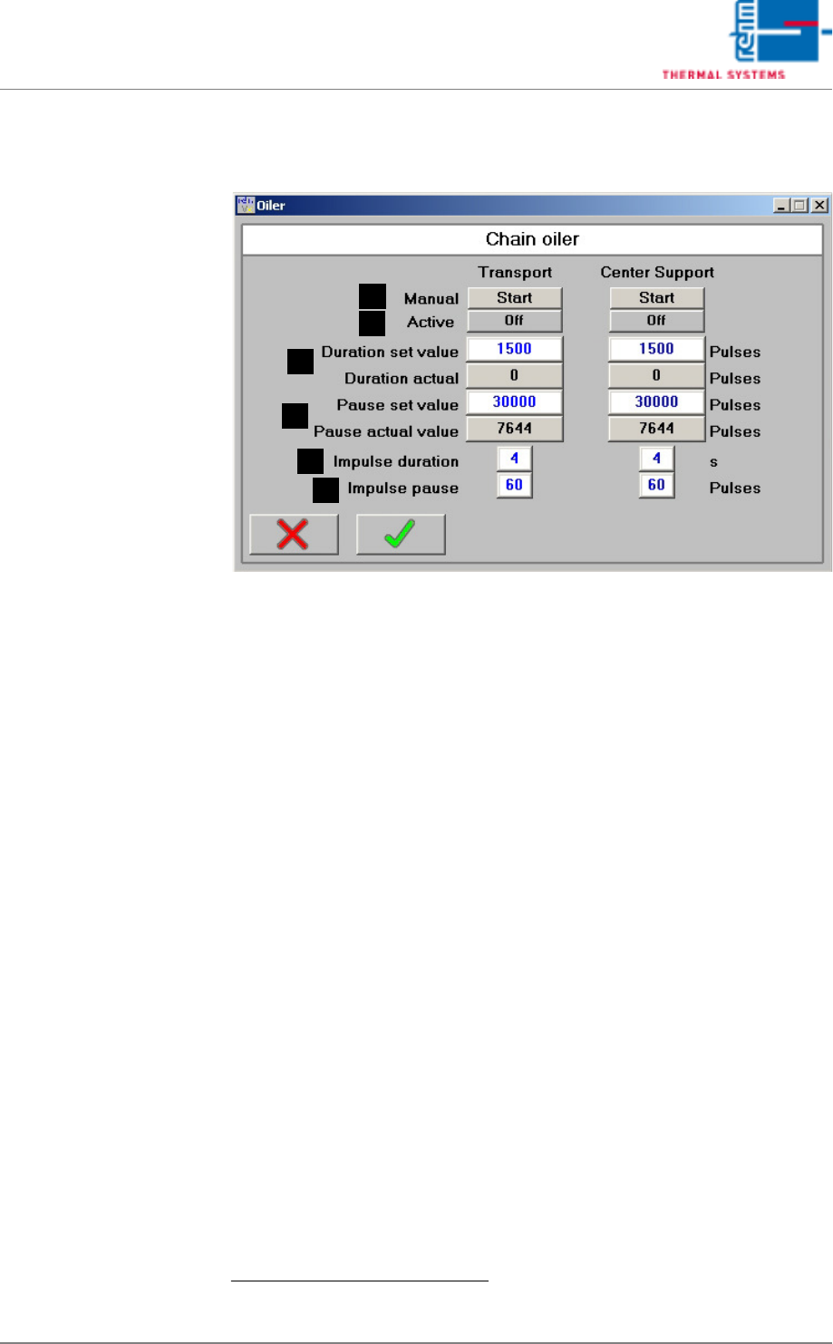
5.5.6 The Chain Lubricator
Fig. 5-44 The Chain Lubricator
The Chain Lubricator window is a virtual timer switch for intervallic control
of the chain lubricator. Chain lubricating intervals and on-time in pulses can
be selected here for the chain lubricating process based upon conveyor belt
pulses generated by the sensor at the drive sprocket.
If the electric magnet is de-energized (interpulse period valve), the pump
pistons are brought into the initial position over spring force and they suck
the chain oil for the next ejection.
A) Start Button
When the chain lubricator is in the pause mode, the chain lubricator is
started manual for the number of pulses specified under duration, after
which pause time is restarted.
B) Status Display
The current status of the chain lubricator is displayed (off or on).
C) Duration
The duration of the active phase is entered to the white field.
1
Duration is
entered in terms of belt pulses.
When the chain lubricator is active, the number of elapsed belt pulses is
displayed in the gray field. During the active phase, the pulse chain lu-
bricator valve function is activated
D) Pause
The duration of the pause between active phases is entered to the white
field. Duration is entered in terms of belt pulses.
1
When the chain lubricator is inactive, the number of elapsed belt pulses
is displayed in the gray field.
1. You can read up on the standard values in the service instructions in the chapter „setting
instructions“.
D
C
B
A
E
F
VISION XP+ VAC Page 115
5 Software
5.5 The Masks Menu
Operating Instructions
Version 1.5
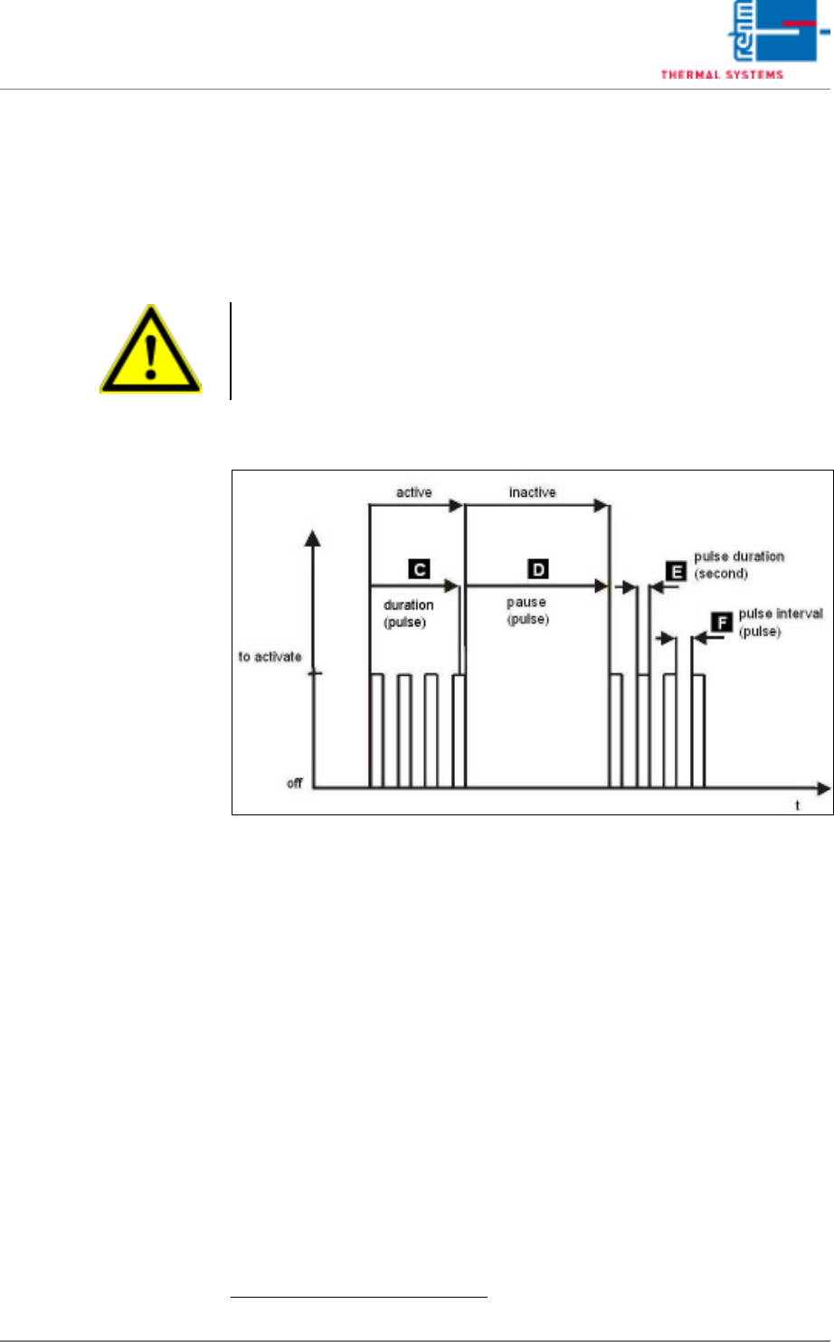
E) Pulse Duration
The duration of a single chain lubricator valve pulse can be selected
here. Duration is entered in seconds.
1
F) Interpulse Period
How much time elapses between chain lubricator valve pulses can be en-
tered here. Duration is entered in pulses.
1
Fig. 5-45 Activation chain lubricator
1.
Note!
The default settings are based upon empirical values. Due to the fact that
actual consumption depends on numerous factors, an individual setting
must be determined by the customer after initial system start-up.
Page 116 VISION XP+ VAC
5 Software
5.5 The Masks Menu
Operating Instructions
Version 1.5
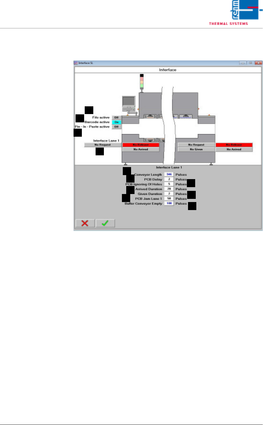
5.5.7 Interfaces
Fig. 5-46 Interface
Values for controlling the interfaces at the system’s inlet and outlet are
displayed here.
A) Belt Length
Number of pulses from the inlet to the outlet (determined at the factory).
B) PCB Delay
Number of pulses during which the light barrier must be obstructed be-
fore a PCB is detected.
C) PCB Hole Suppression
Distance specified for spanning holes in PCBs which do not obstruct the
light barrier (expressed in terms of pulses).
D) Arrival Duration
Number of pulses by which the “Arrival” signal is counted after the PCB
clears the light barrier at the inlet.
E) Discharge Duration
Number of pulses by which the “Discharge” signal is counted after the
PCB clears the light barrier at the outlet.
F) PCB jam lane 1
A number of impulses, after them the alarm „handing over pile-up“ is trig-
gered off when covering the outlet light barrier.
D
C
B
A
E
F
G
H
I
J
K