OperationInstruction_Vsision XP - 第128页
Page 120 V ISION XP+ V AC 5 Software 5.5 The Masks Menu Operating Instructions V ersion 1.5 ed. It remai ns o pen until the system is once ag ain empty for the first time after the purgi ng pha se. The reafter , i t is a…
VISION XP+ VAC Page 119
5 Software
5.5 The Masks Menu
Operating Instructions
Version 1.5
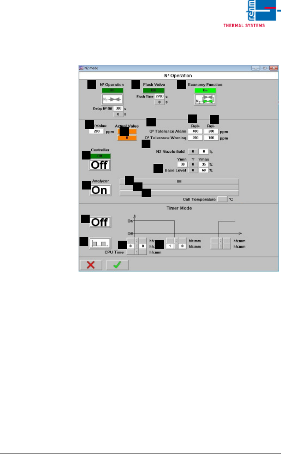
5.5.9 N2 Operating Mode
Fig. 5-48 N2 Operating Mode
Note!
Timer Mode:
The timer function is deactivated when the nitrogen control is working.
A) N2 Operation
On: Soldering is executed in a nitrogen atmosphere, servo-valves are
open. Off: Soldering is executed in air, servo-valves are closed in a time
delayed fashion. It is also possible to enter after how much delay time in
seconds nitrogen operation when switching off the heating is deactivated.
B) Flush Valve
After nitrogen operation has been activated, a scavenging valve is addi-
tionally opened for an adjustable period of time. Specified time can be ad-
justed here, and elapsed time can be monitored. Valve status is
displayed. The process chamber is opened, N2 operation is stopped im-
mediately. The purging phase is started over from the beginning after the
system has once again been completely closed.
C) Saving function (optional)
The economy mode option monitors the system’s loading status. An ad-
ditional control valve is opened after nitrogen operation has been activat-
CBA
F
Q
J
G
K
D
R
S
O
P
N
E
M
L
H
I

Page 120 VISION XP+ VAC
5 Software
5.5 The Masks Menu
Operating Instructions
Version 1.5
ed. It remains open until the system is once again empty for the first time
after the purging phase. Thereafter, it is always open when the system is
loaded. This function can be deactivated here. The valve is always open
in this case.
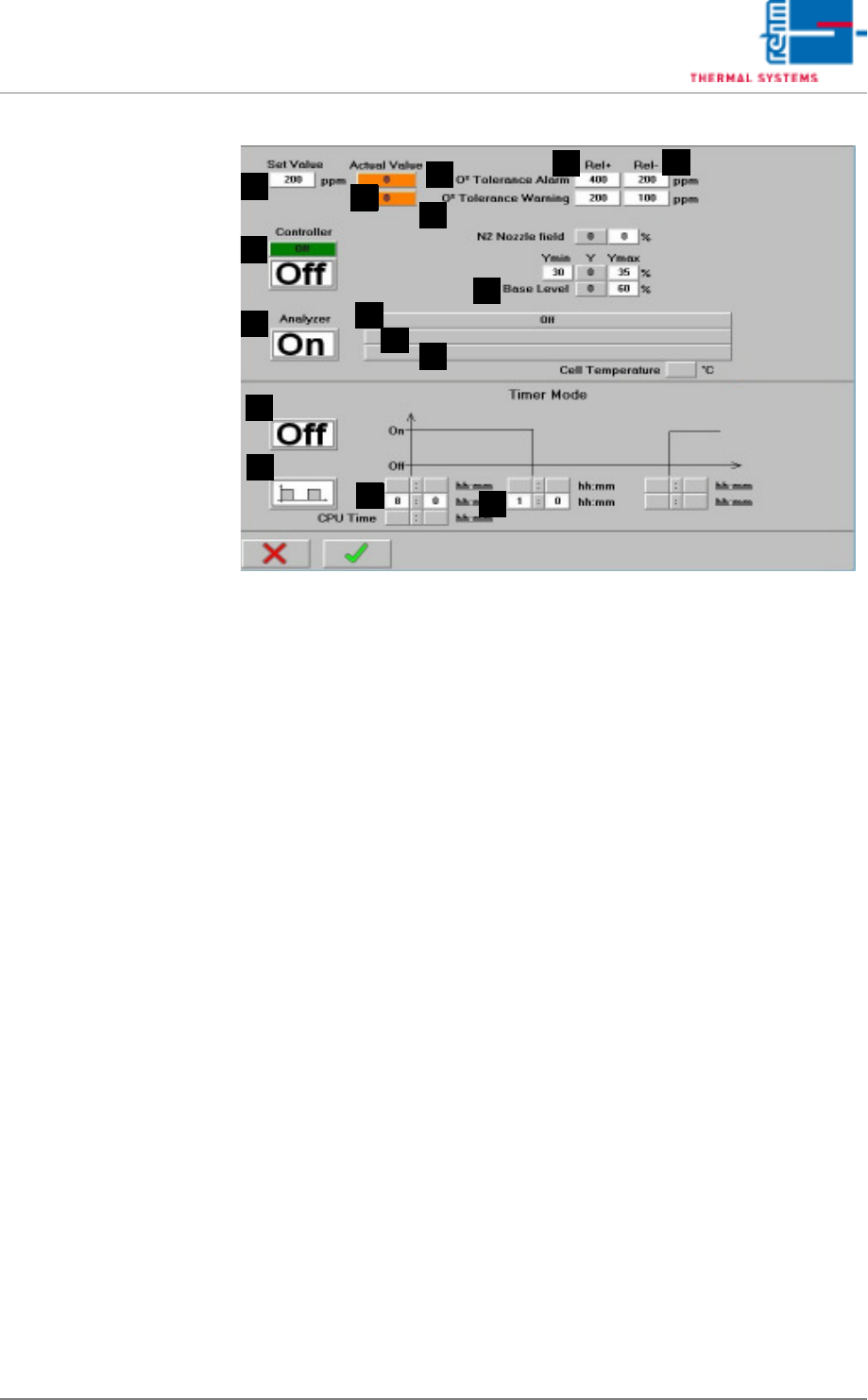
D) Set Value
Entry field for the residual oxygen setpoint.
E) Actual Value
Residual oxygen content display. If the residual oxygen meter does not
yet ready the display shows 999999.
F) Rel+
The relative upper tolerance limit can be selected here, relative to the
setpoint.
G) Rel-
The relative lower tolerance limit can be selected here, relative to the set-
point.
H) O2 tolerance violation
If the tolerance is exceeded or fallen short of, the “O2 tolerance” alarm is
triggered. No further work can be performed. In the flushing phase or af-
ter the program change until the set value is achieved for the first time,
no buzzer sounds with this alarm.
I) O2 tolerance warning (option)
This is a preliminary warning which precedes the “O2 tolerance” alarm. A
horn sounds if the tolerance is exceeded or fallen short of. Work can nev-
ertheless be continued.
J) Control mode
The control mode can be activated by entering different values for Y-min
and Y-max, and setting the Control mode button to ON.
Y-min = min. opening for N2 control valve
Y-max = max. opening for N2 control valve
Y = current setting is displayed.
K) Base Level
The valve's manipulated variable is set here for the basic level.
L) Oxygen meter on/off
The residual oxygen meter can be switched on and off here.
VISION XP+ VAC Page 121
5 Software
5.5 The Masks Menu
Operating Instructions
Version 1.5
Fig. 5-49 N2 Operating Mode (excerpt)
M) Display of oxygen meter operating state
Possible states
Off: The oxygen meter is switched off.
Cycle mode active: oxygen meter on
timer mode on
cycle mode
The oxygen meter is performing a measurement.
Cycle mode inactive: oxygen meter on
timer mode on
cycle mode
The oxygen meter is pausing between measurement.
Clock time mode active: oxygen meter on
timer mode on
clock time mode
The oxygen meter is performing a measurement.
Clock time mode inactive: oxygen meter on
timer mode on
cycle mode
The oxygen meter is pausing between measurement.
Continuous operation: oxygen meter on
timer mode off
Continuous measurement is performed with the residual oxygen meter.
Measurement after opening active: oxygen meter on
timer mode on
cycle mode or clock time mode
The process chamber has been opened and then closed again.
Measurement is thus started for a fixed period of 1 hour.
F
Q
J
G
K
R
T
S
O
P
N
E
M
L
H
I