OperationInstruction_Vsision XP - 第185页
V ISION XP+ V AC Page 177 7 Alarm Messages Operating Instructions V ersion 1.5 7 Alarm Messages The following pages include explanations of all alarm messages which might appear at the alarm window . Depending upon syste…
Page 176 VISION XP+ VAC
6 Rehm Recorder
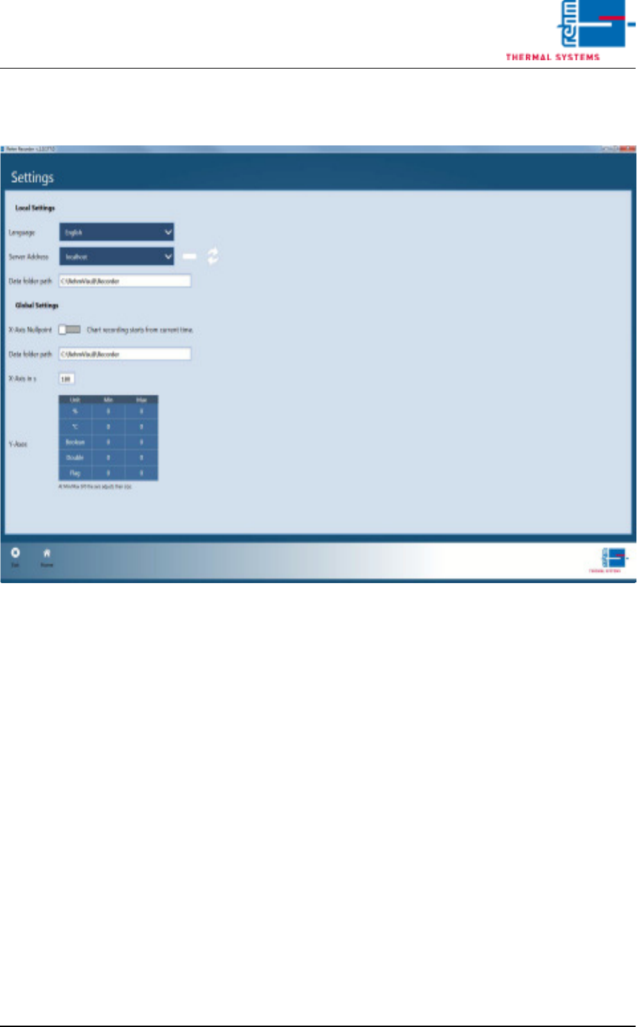
6.5 Settings
Operating Instructions
Version 1.5
6.5.2 Save settings
Fig. 6-31 Save settings
If you exit the settings via the "Home" button, the application asks whether
you wish to save the changes.
Confirming with "Yes" saves the changes. Otherwise the changes are dis-
carded and the old configuration is retained.
VISION XP+ VAC Page 177
7 Alarm MessagesOperating Instructions
Version 1.5
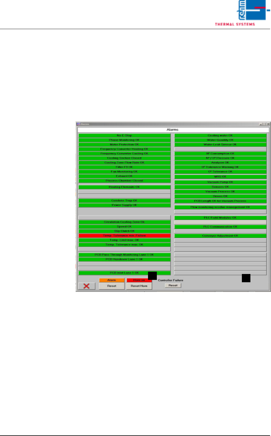
7 Alarm Messages
The following pages include explanations of all alarm messages which might
appear at the alarm window.
Depending upon system version, the alarms are either actively displayed in
the window, or appear in gray if the corresponding options are not integrated
into the system.
Fig. 7-1 Window with Alarm Messages
Tips regarding causes and troubleshooting are included as well.
The way the system reacts in response to the various alarms is described in
the Alarm Configuration section of the service instructions.
A) Button for switching the horn off. This is the same function which appears
in the main window.
B) Horn Switch
The horn sounds to indicate alarm messages which this switch is turned
on. If, on the other hand, the switch is turned off, alarm messages appear
at the display only. the horn does not sound.
A
B
Page 178 VISION XP+ VAC
7 Alarm Messages
7.1 Emergency-Stop Activated
Operating Instructions
Version 1.5
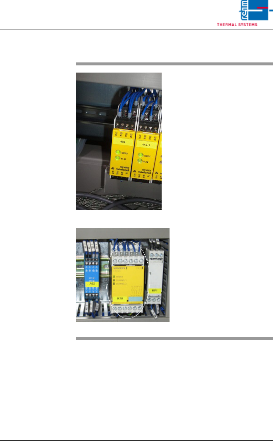
7.1 Emergency-Stop Activated
Fig. 7-2 Emergency-Stop Relay
Fig. 7-3 Emergency-Stop Relay by Siemens
By pressing the emergency stop
button all electromechanical move-
ments are switched off.
IMPORTANT!
If the system is heated (> 90 ° C),
the heater fan motor is to protect
against this accumulated heat.
Procedure:
1. All dangers / errors must be
eliminated.
2. The EMERGENCY STOP but-
ton unlock mechanically by ro-
tating counterclockwise. Thus,
the emergency stop circuit is
closed again.
3. In the main mask click the Re-
set Emergency-Stop button
(see Fig. 5-10 on page 82) and
then the Alarm button (see Fig.
5-10 on page 82) in the main
window.
4. The alarm window appears
(see Fig. 7-1, page 177). Click
the Reset Alarm button in this
window.
5. In the main window click under
Drive and heat are on, the but-
ton at the right for switching the
heat on.