OperationInstruction_Vsision XP - 第187页
V ISION XP+ V AC Page 179 7 Alarm Messages 7.2 Phase Monitoring T ripped Operating Instructions V ersion 1.5 7.2 Phase M onitoring T ripped 7.3 Motor O verload Protection T ripped Fig. 7-4 Phase M onitoring Relay The fus…
Page 178 VISION XP+ VAC
7 Alarm Messages
7.1 Emergency-Stop Activated
Operating Instructions
Version 1.5
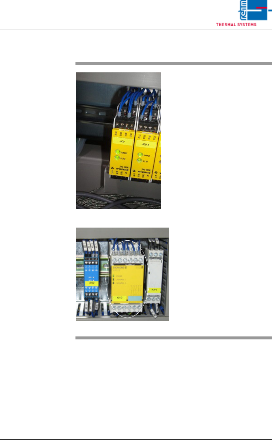
7.1 Emergency-Stop Activated
Fig. 7-2 Emergency-Stop Relay
Fig. 7-3 Emergency-Stop Relay by Siemens
By pressing the emergency stop
button all electromechanical move-
ments are switched off.
IMPORTANT!
If the system is heated (> 90 ° C),
the heater fan motor is to protect
against this accumulated heat.
Procedure:
1. All dangers / errors must be
eliminated.
2. The EMERGENCY STOP but-
ton unlock mechanically by ro-
tating counterclockwise. Thus,
the emergency stop circuit is
closed again.
3. In the main mask click the Re-
set Emergency-Stop button
(see Fig. 5-10 on page 82) and
then the Alarm button (see Fig.
5-10 on page 82) in the main
window.
4. The alarm window appears
(see Fig. 7-1, page 177). Click
the Reset Alarm button in this
window.
5. In the main window click under
Drive and heat are on, the but-
ton at the right for switching the
heat on.
VISION XP+ VAC Page 179
7 Alarm Messages
7.2 Phase Monitoring Tripped
Operating Instructions
Version 1.5
7.2 Phase Monitoring Tripped
7.3 Motor Overload Protection Tripped
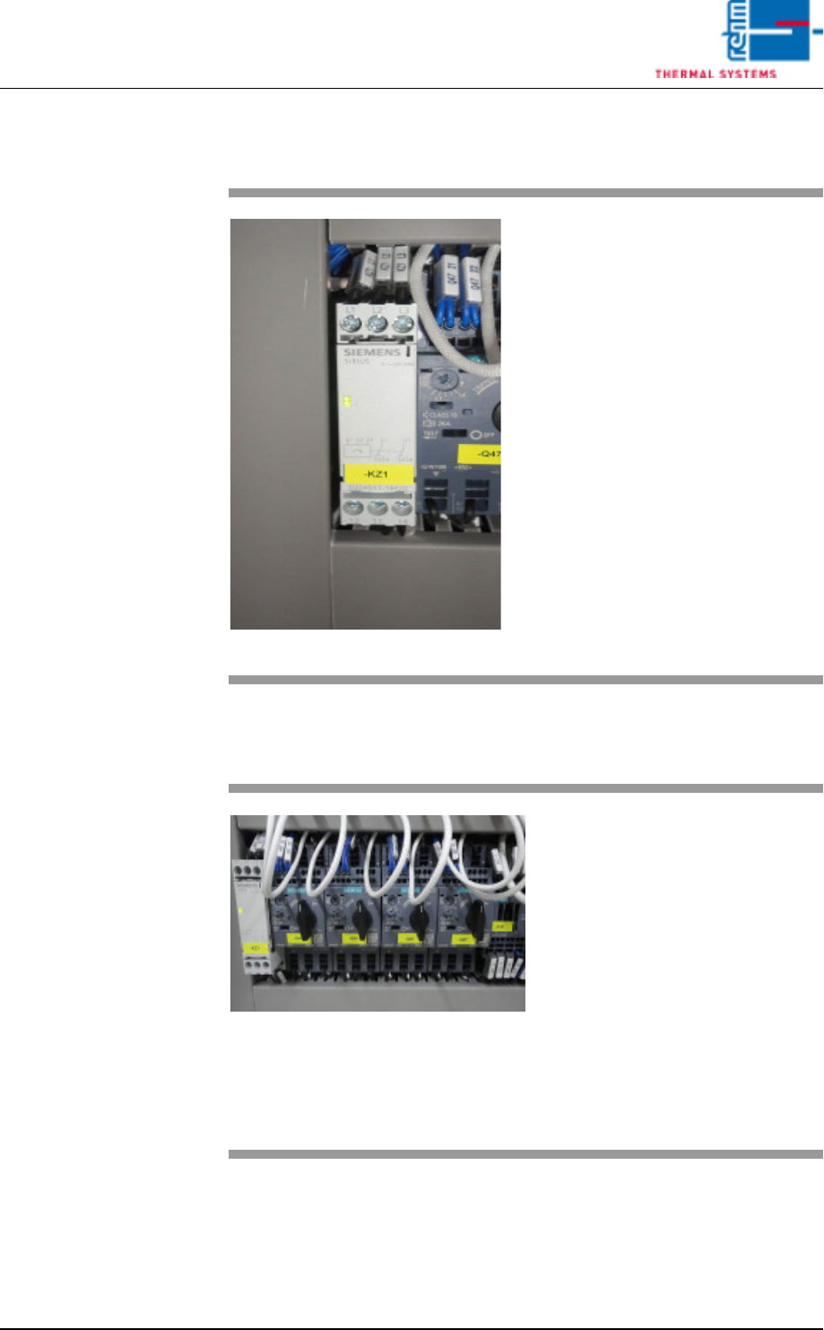
Fig. 7-4 Phase Monitoring Relay
The fuse F5 has triggered.
Procedure:
• Arrange for repair by a qualified
electrician.
If the relay indicator lights up, all
phases are OK.
Fig. 7-5 Motor Protection Relay
One or more protective motor
switches have been tripped.
Procedure:
• Check the motor switches.
• Check corresponding motor and
attached mechanical devices for
correct functioning.
• Reset motor protection.
• If the fault recurs, make sure that
the current setting at the relay
complies with the circuit diagram,
and measure current.
Page 180 VISION XP+ VAC
7 Alarm Messages
7.4 Frequency Converter
Operating Instructions
Version 1.5
7.4 Frequency Converter
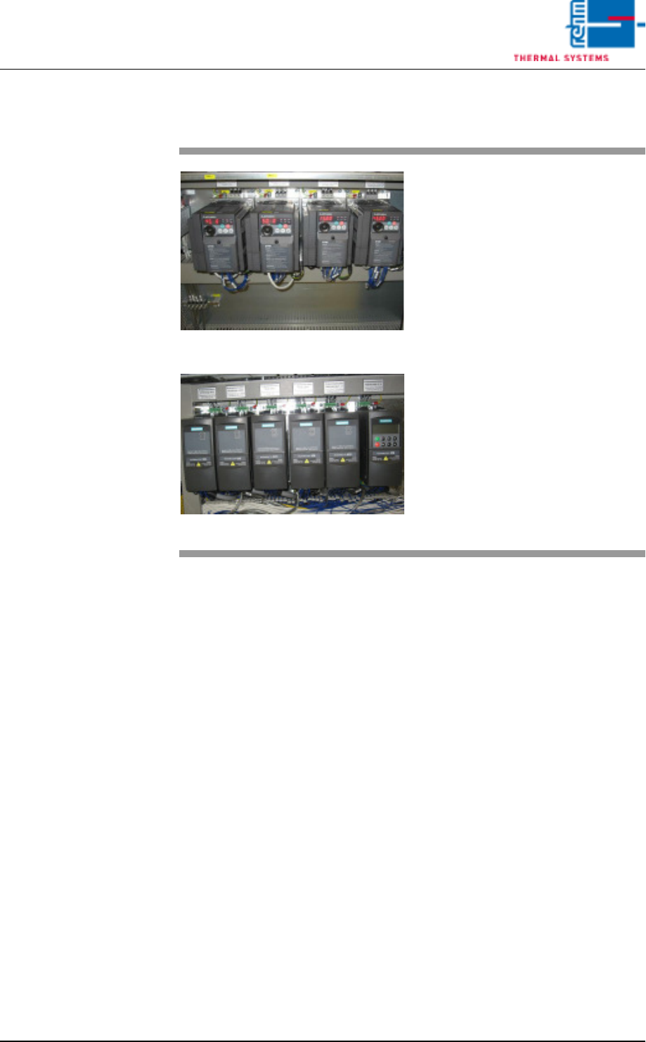
Fig. 7-6 Frequency Converter
Fig. 7-7 Frequency Converter by Siemens
A frequency converter has triggered
the error message.
Procedure:
• Check the frequency converter in
the control cabinet.
• Inspect the fuse.
• Determine the fan defect of the
heating or the cooling zone.
• Control the fans (whether they are
dirty).
• Reset the frequency converter.
Refer to the included frequency
converter operating instructions
to this end.