OperationInstruction_Vsision XP - 第199页
V ISION XP+ V AC Page 191 7 Alarm Messages 7.30 Cooling system failure (option) Operating Instructions V ersion 1.5 7.30 Coolin g system failure (opt ion) External c ooling Procedure : • Check exter nal cooling equipmen …
Page 190 VISION XP+ VAC
7 Alarm Messages
7.28 Water amount is too low (option)
Operating Instructions
Version 1.5
7.28 Water amount is too low (option)
7.29 Water Leak (option)
Possible causes:
• The water system has a leak.
• There’s no water in the tank.
• The sensor is defective.
Procedure:
• Inspect all tubing and connections within the water system, and repair if
necessary.
• Fill the water tank.
• Inspect the sensor and replace if necessary.
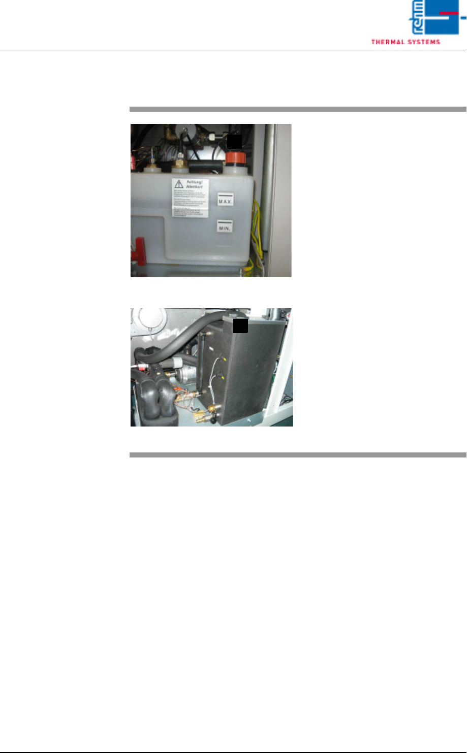
Fig. 7-20 Tank with Water Level Sensor
Fig. 7-21 Tank with Water Level Sensor CN
Possible causes:
• There is too little water in the tank.
• The sensor is defective.
Procedure:
• Fill in the mixture of cooling water
in (E) by means of a watering can.
• Inspect the sensor.
E
E
VISION XP+ VAC Page 191
7 Alarm Messages
7.30 Cooling system failure (option)
Operating Instructions
Version 1.5
7.30 Cooling system failure (option)
External cooling
Procedure:
• Check external cooling equipment. Switch on or repair external cooling
equipment.
• Check temperature setpoint and hysteresis. Correct selected values.
• Check coolant water level and replenish if necessary.
7.31 N2 consumption OK / too high (option)
Only with N2 consumption measuring. In the „Consumption Parameter“
mask a limit value is set. If it is exceeded, the alarm is triggered off (not in
the flushing phase).
7.32 N2/O2 Pressure Too Low (option)
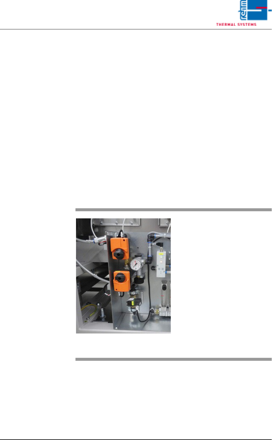
Fig. 7-22 Servomotor, Main N2 Supply Line
The alarm is only activated in the
event of operation with nitrogen.
Possible causes:
• Gas pressure is too low or nonex-
istent.
• Supply pressure has fallen below
the selected alarm value.
• The heat is turned off. The Belimo
servomotor in the main N2/O2
supply line is closed.
Procedure:
• Inspect the N2/O2 supply line.
• 5bar Control
• 3m³/h pyrolyses
Page 192 VISION XP+ VAC
7 Alarm Messages
7.33 Residual Oxygen Meter Malfunction
Operating Instructions
Version 1.5
7.33 Residual Oxygen Meter Malfunction
7.34 O² tolerance warning
Advance warning for Residual oxygen valve.
7.35 O
2
Tolerance injury
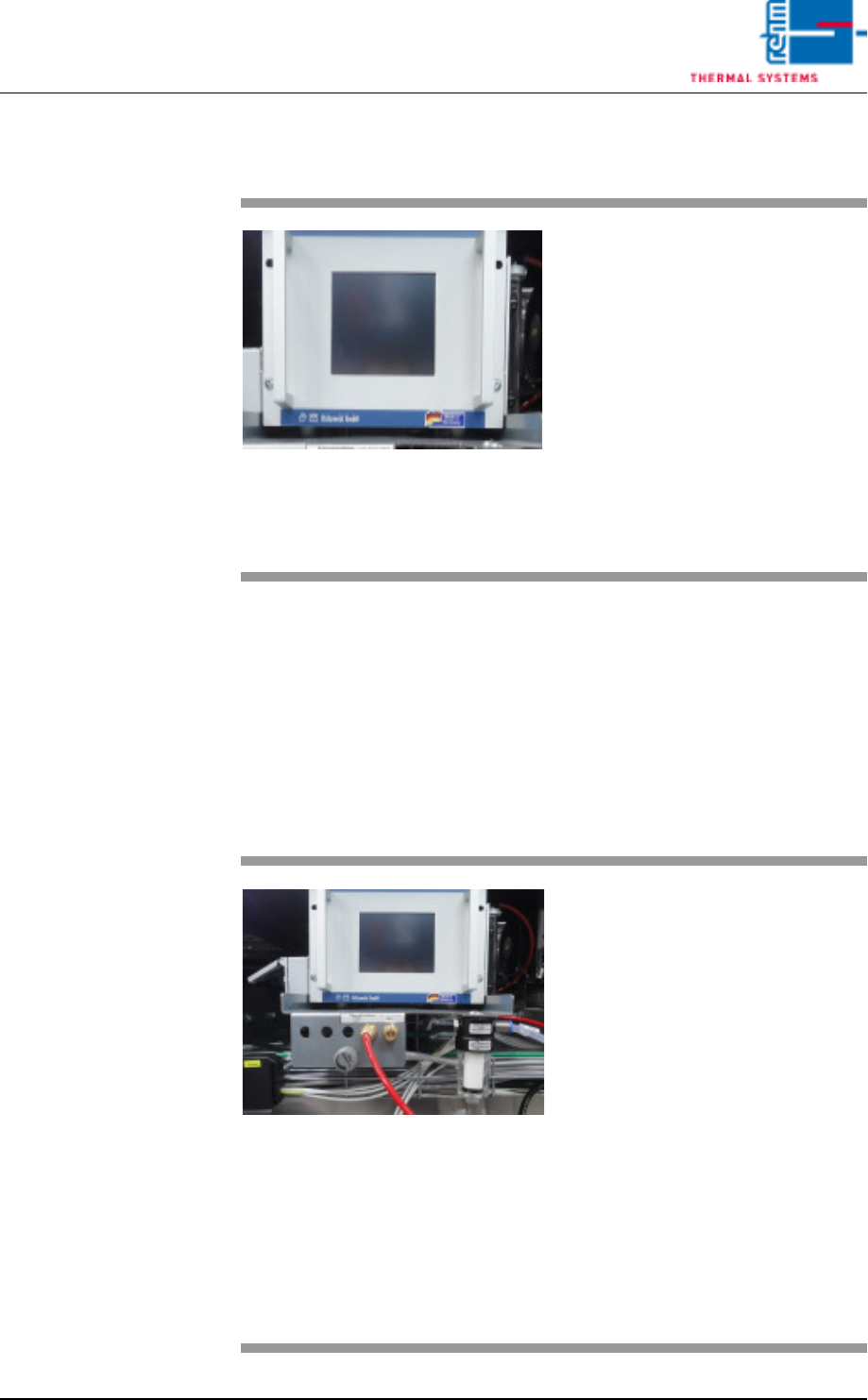
Fig. 7-23 Residual Oxygen Meter
An error has occurred at the residu-
al oxygen meter.
Possible causes:
• Flow is impaired.
• The filter at the residual oxygen
meter is contaminated.
• Residual oxygen meter is defect
Please refer to the included docu-
mentation regarding the
residual oxygen meter for additional
details.
Fig. 7-24 Nitrogen Connections and Residu-
al Oxygen Meter
The residual oxygen value in the
heating chamber has exceeded the
value set in the N2 operation mask
limit tolerance value.
Possible causes:
• Inadequate maintenance.
• The nitrogen settings are incor-
rect. Check the fixed settings in
the calibration report!
• One of the process chamber
seals is leaky.
• The residual oxygen meter is
hooked up incorrectly (standard:
peak zone).
• The filter bowl in the peak zone is
contaminated.