OperationInstruction_Vsision XP - 第203页
V ISION XP+ V AC Page 195 7 Alarm Messages 7.43 Dropped Board Monitoring OK (option) Operating Instructions V ersion 1.5 7.43 Dropp ed Board M onitorin g OK (o ption) By falling d own a board in th e system, a contac t i…
Page 194 VISION XP+ VAC
7 Alarm Messages
7.40 Filling level chain oiler is too low (option)
Operating Instructions
Version 1.5
7.40 Filling level chain oiler is too low (option)
The storage tank of the chain oiler is almost empty.
Procedure:
• Refill the storage tank.
7.41 PLC Field Modules
7.42 PLC Communication
An alarm message is generated when communication between the PC and
the PLC is interrupted.
Possible causes:
• The Ethernet cable between the PLC and the PC is defective, or has not
been plugged in.
Procedure:
• Replace the defective component or plug in the cable.
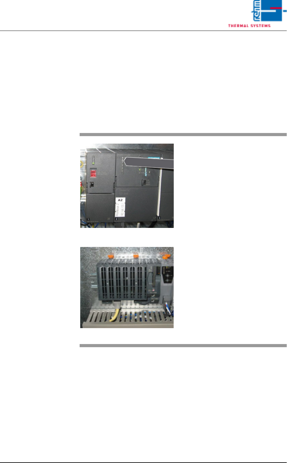
Fig. 7-25 CPU with Siemens-control
Fig. 7-26 CPU with B&R-control
The alarm message „field modules
PLC“ is displayed when there is a
fault in the control.
This may also be a consequential
error caused by an emergency stop.
Possible Causes:
• cable defective
• Modul defective
• Short-circuit on module
Procedure:
• Make sure that all cables are con-
nected to the PLC.
• Make sure that all of the respec-
tive components are plugged into
the PLC.
• Check whether a red LED lights
up on a module.
VISION XP+ VAC Page 195
7 Alarm Messages
7.43 Dropped Board Monitoring OK (option)
Operating Instructions
Version 1.5
7.43 Dropped Board Monitoring OK (option)
By falling down a board in the system, a contact is closed causing the alarm.
7.44 Transport adjustment OK / failure
It is triggered of with the transport during time out adjustment. Elimination
through „Alarm-Reset“. With it the timeout failure is reset. Software would
proceed, but gets no response from the encoder.
7.45 Conveyor Adjustment Current (option)
7.46 Conveyor Drive Current (option)
The alarm message is triggered when the actual value is greater than the
setpoint.
Possible causes:
• Excessive current.
• When the conveyor is contaminated, the motor requires more power in or-
der to maintain the specified speed.
Procedure:
• The conveyor should be cleaned and lubricate at certain intervals.
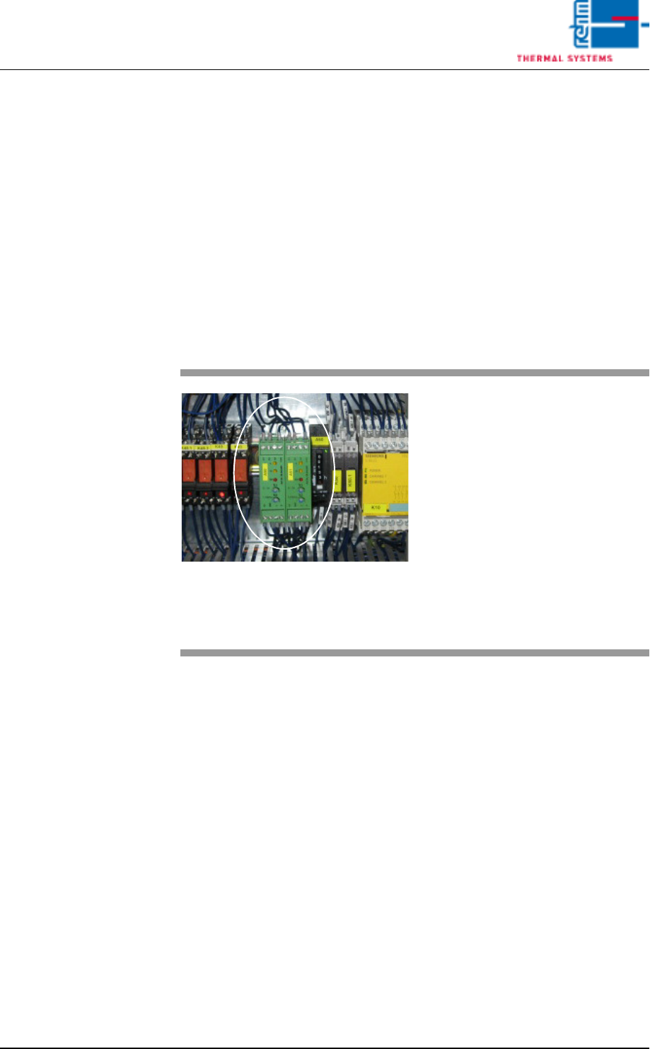
Fig. 7-27 Motor Controller
If one of the conveyor adjustment
motors is overloaded, the “Convey-
or Adjustment Current” message is
displayed.
Procedure:
• Check the mechanic stations if
they are damage (parts).
• Check all of the conveyor adjust-
ment components for correct
mounting.
• Clean, lubricate, adjust and/or fix
the conveyor adjustment system.

Page 196 VISION XP+ VAC
7 Alarm Messages
7.47 The oven is locked by MES
Operating Instructions
Version 1.5
7.47 The oven is locked by MES
The oven is locked by the superior MES-System.