OperationInstruction_Vsision XP - 第204页
Page 196 V ISION XP+ V AC 7 Alarm Messages 7.47 The oven is locked by MES Operating Instructions V ersion 1.5 7.47 The oven is locke d by MES The oven is lock ed by the superior MES-System.
VISION XP+ VAC Page 195
7 Alarm Messages
7.43 Dropped Board Monitoring OK (option)
Operating Instructions
Version 1.5
7.43 Dropped Board Monitoring OK (option)
By falling down a board in the system, a contact is closed causing the alarm.
7.44 Transport adjustment OK / failure
It is triggered of with the transport during time out adjustment. Elimination
through „Alarm-Reset“. With it the timeout failure is reset. Software would
proceed, but gets no response from the encoder.
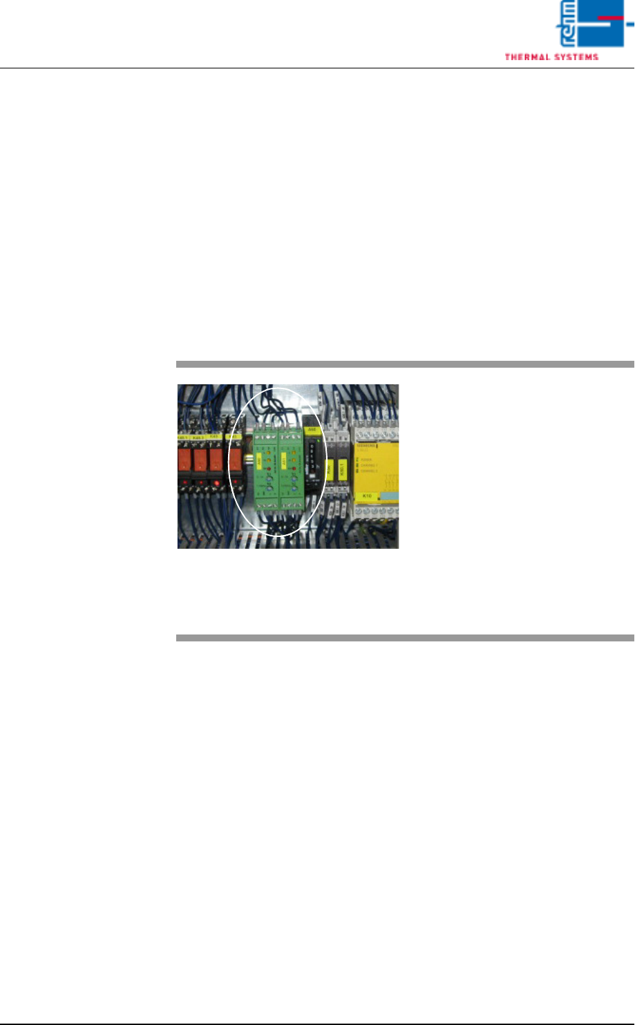
7.45 Conveyor Adjustment Current (option)
7.46 Conveyor Drive Current (option)
The alarm message is triggered when the actual value is greater than the
setpoint.
Possible causes:
• Excessive current.
• When the conveyor is contaminated, the motor requires more power in or-
der to maintain the specified speed.
Procedure:
• The conveyor should be cleaned and lubricate at certain intervals.
Fig. 7-27 Motor Controller
If one of the conveyor adjustment
motors is overloaded, the “Convey-
or Adjustment Current” message is
displayed.
Procedure:
• Check the mechanic stations if
they are damage (parts).
• Check all of the conveyor adjust-
ment components for correct
mounting.
• Clean, lubricate, adjust and/or fix
the conveyor adjustment system.

Page 196 VISION XP+ VAC
7 Alarm Messages
7.47 The oven is locked by MES
Operating Instructions
Version 1.5
7.47 The oven is locked by MES
The oven is locked by the superior MES-System.

VISION XP+ VAC Page 197
Page
List of figures
Operating Instructions
Version 1.5
List of Figures
Zones Fig. 1-2 7
Activation chain lubricator Fig. 5-45 115
Active cooling module Fig. 4-42 65
Back button Fig. 6-6 156
Band pulse sensor Fig. 7-16 185
Bushing Chain Conveyor Fig. 4-10 50
Calculate gradient Fig. 6-20 167
CCS Sensor Fig. 4-18 53
Center Board Support Fig. 4-13 51
Chain Tensioners Fig. 4-14 51
Change settings Fig. 6-30 174
Changing a Password Fig. 5-20 91
Checkbox ticked Fig. 6-19 165
Company Headquarters, Rehm Thermal Systems GmbH Fig. 1-1 3
Compressed Air and Nitrogen Unit Fig. 4-54 71
Condensate Trap VXP+ Fig. 4-48 68
Configuration selection Fig. 6-10 160
Control Cabinet, Section 1 (with B&R-control) Fig. 4-59 74
Control Cabinet, Section 1 (with Siemens-control) Fig. 4-58 74
Control Cabinet, Section 2 Fig. 4-60 75
Control Cabinet, Section 3 Fig. 4-61 76
Control Cabinet, Section 4 Fig. 4-62 76
Conveyor Belt Pulse Sensor and Slip Clutch Fig. 4-16 52
Conveyor Chain Fig. 7-15 185
Conveyor Values Fig. 5-43 112
Cooling System Components CN Fig. 7-19 189
Cooling System Components Fig. 7-18 189
Cooling system with integrated coolant water pump CN Fig. 4-53 70
Cooling system with integrated coolant water pump Fig. 4-52 70
Cooling tract circulation Fig. 7-14 184
CPU with B&R-control Fig. 7-26 194
CPU with Siemens-control Fig. 7-25 194
Create new configuration button Fig. 6-3 155
CS Height Adjustment Fig. 4-20 54
CS Leaf Chain Fig. 4-19 54
Current monitoring module Fig. 7-11 182
Data recording 1 Fig. 6-16 163
Data recording legend Fig. 6-18 165
Differential pressure gauge for cvolume flow measurement Fig. 4-39 63
Dimensions with Wooden Crate Fig. 3-5 32
Dimensions Fig. 3-1 30
Display Elements and Controls Fig. 4-2 42
Display PCB Fig. 5-57 130
Displaying the Protocol as a Table Fig. 5-63 139
Edit configuration name Fig. 6-4 155
Edit Protocol Definition (events window) Fig. 5-62 137
Electrical Connection Fig. 3-11 36
Emergency-Stop Buttons Fig. 4-5 43
Exhaust air connection Fig. 3-10 35
Exhaust Air System with Connection for a Plant Exhaust System Fig. 4-50 69