OperationInstruction_Vsision XP - 第49页
Vision XP+ V AC Page 41 4 Equipment 4.1 System Segments Operating Instructions V ersion 1.5 4 Equipment Some of the comp onents l isted in this chapter are options, and may vary de- pending up on system variant. 4.1 Syst…
Page 40 Vision XP+ VAC
3 From Transport to Initial Start-Up
3.5 Switching the System Off
Operating Instructions
Version 1.5
3.5 Switching the System Off
Proceed as follows in order to switch the system off:
1. Make sure that the system is completely empty of PCBs.
2. Click the Heat On/Off software button in order to switch the heaters off.
Click the Drive On/Off software button in order to switch the conveyor
off.
3. Or shut the system down by means of the auto-off program.
4. The fans in the heating zones and the conveyor continue to run in order
to assure complete cool-down, and to prevent damage to the motors.
5. The cool-down cycle is controlled by measuring temperature at the heat-
ers and the watchdogs. After the temperature at all measuring points
has fallen below the selected setpoint for the cooling cycle, the fans in
the heat zones and the conveyor are switched off.
6. Click “Exit” in the “System” menu in order to close the system software.
7. Shut down the operating system.
8. Turn off the uninterruptible power supply (optional) with the On/Off but-
ton.
9. Turn the system off with the mains switch.
3.6 Storage
If the system is shut down and stored, we recommend to store the system
dust-free, dry and at the temperature from -25°C to +55°C.
To avoid further damages, you should rinse the water carrying pipes with an-
tifreeze agent with the danger of frost.
Warning!
During operation, the system may only be switched off with the mains
switch in the event of an emergency.
Shut down the operating system properly before switching the system off.
If the system is switched off during operation without first properly shutting
down the operating system, the cool-down cycle is not activated and the
system, as well as the PC, may be damaged.
Warning!
Never switch the system off before the cool-down cycle has been complet-
ed. The system might otherwise be damaged as the result of heat
accumulation.
Vision XP+ VAC Page 41
4 Equipment
4.1 System Segments
Operating Instructions
Version 1.5
4 Equipment
Some of the components listed in this chapter are options, and may vary de-
pending upon system variant.
4.1 System Segments
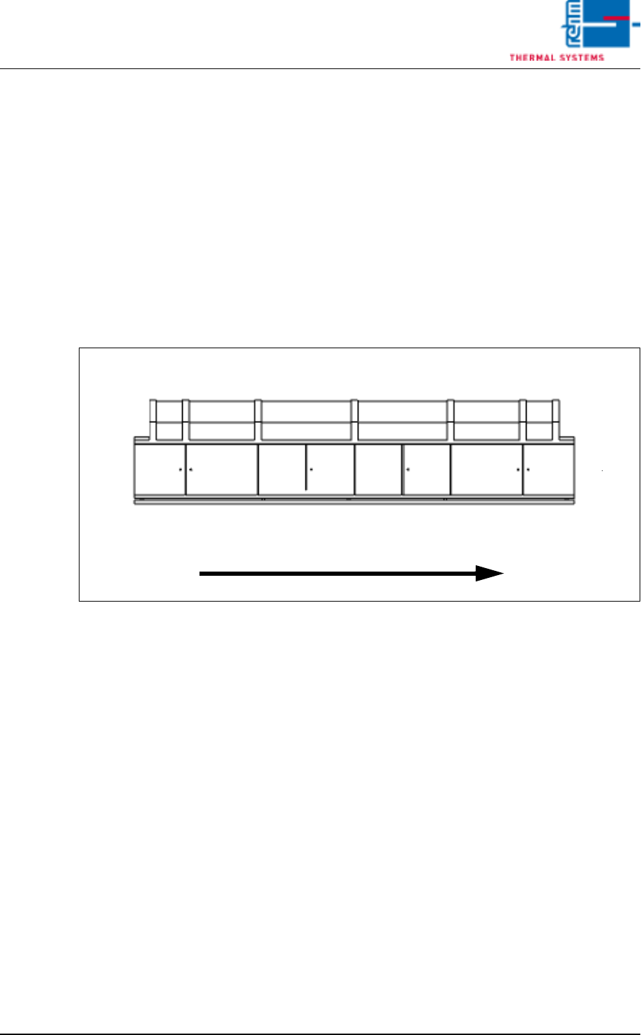
The individual system segments are represented as schematic drawings in
the following graphics. The terms specified for the segments in the graphic
are utilized throughout these operating instructions as well.
Fig. 4-1 System Segments
System Rear Panel
Inlet
Preheating
Peak
Cooling Tract
Outlet
Operating Side
Transport Direction
Zone
vacuum zone
Page 42 Vision XP+ VAC
4 Equipment
4.2 Display Elements and Controls on the System
Operating Instructions
Version 1.5
4.2 Display Elements and Controls on the System
4.2.1 Mains Switch
Note!
Emergency-Off-function main switch
The main switch (Q1) is a superior safety-switch unit, over which the com-
plete system „OFF“ can be switched (disconnected from network). This
switch unit should only be activated, when there is a personal danger to life
and limb, as the PC and the fans of the heating and cooling zones will also
be switched off here.
Fig. 4-2 Display Elements and Controls
A)Indicator lamp
B)Monitor screen
C)Keyboard
D)Emergency-stop buttons
E)Mains switch (red switch)
C
B
A
E
D
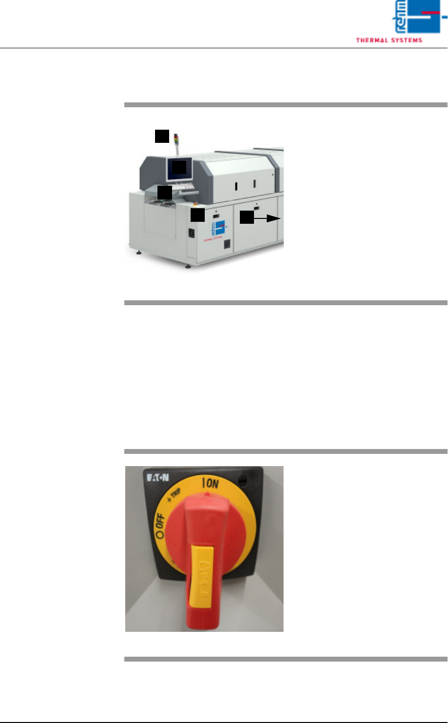
Fig. 4-3 Mains Switch
The mains switch is located at the
rear section on the operator side of
the machine.
It is only required for switching the
system’s power supply on and off
for service and maintenance work.
Caution! Life Endangering!
The mains switch is an integral part
of the power supply system. Even
when the mains switch is turned off,
certain components inside the sys-
tem still conduct life endangering
voltage.