OperationInstruction_Vsision XP - 第53页
Vision XP+ V AC Page 45 4 Equipment 4.2 Display Elements and Controls on the System Operating Instructions V ersion 1.5 4.2.6 M onitor Screen Fig. 4-8 Monitor S creen wi th Keybo ard The monitor sc reen and the key- boar…
Page 44 Vision XP+ VAC
4 Equipment
4.2 Display Elements and Controls on the System
Operating Instructions
Version 1.5
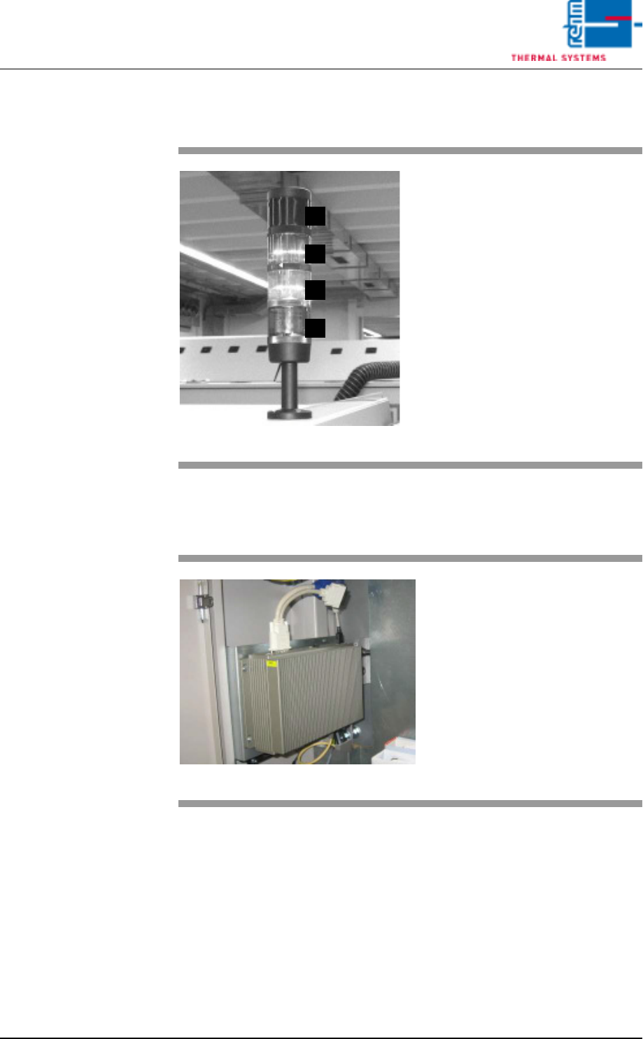
4.2.4 Indicator Lamp
4.2.5 Industrial PC
Fig. 4-6 Indicator Lamp
A)Horn
The horn sounds in the event of
severe malfunctions.
B)Group fault
Lights up when a fault occurs
which requires an intervention of
the operator.
C)Service mode operation
System is switched on, not ready
for operation
D)Ready for operation
Lights up when the system is
ready for operation.
D
C
B
A
Fig. 4-7 Industrial PC
Industrial PC´s are applied in all
Rehm – systems.
Vision XP+ VAC Page 45
4 Equipment
4.2 Display Elements and Controls on the System
Operating Instructions
Version 1.5
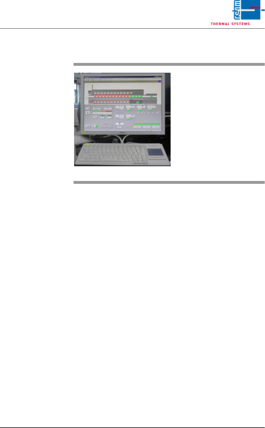
4.2.6 Monitor Screen
Fig. 4-8 Monitor Screen with Keyboard
The monitor screen and the key-
board are on top of a rotating con-
sole on the system.
The graphic user interface (based
on the Windows standard) is used
to operate and monitor the system.
A color monitor with a resolution of
1280 x 1024 pixels is utilized for
display purposes.
Page 46 Vision XP+ VAC
4 Equipment
4.2 Display Elements and Controls on the System
Operating Instructions
Version 1.5
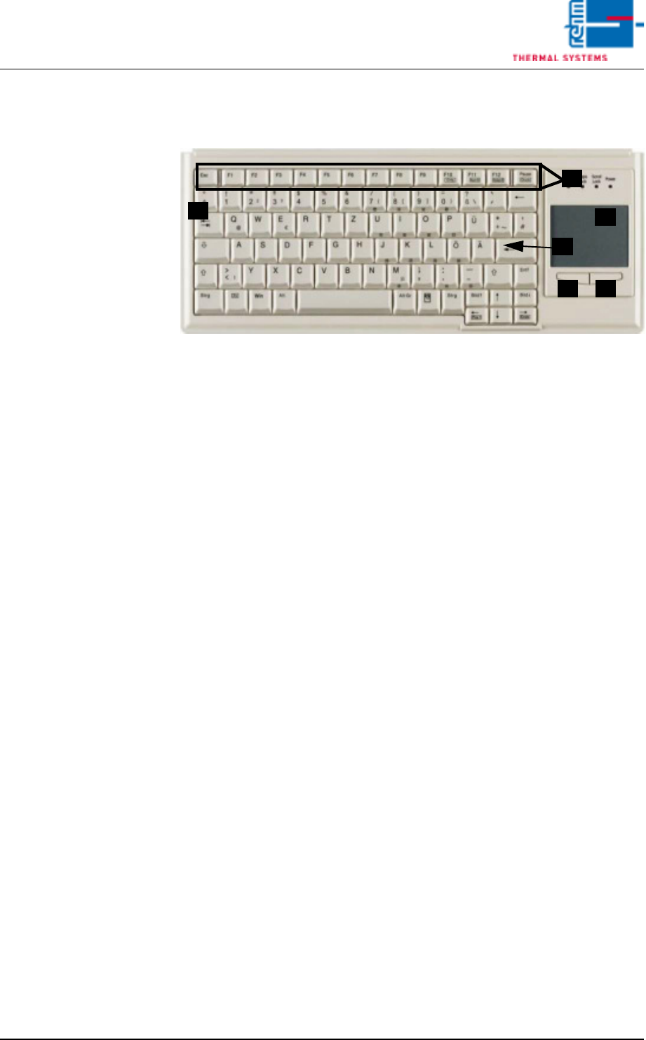
4.2.7 Keyboard
Fig. 4-9 Keyboard
A) Function keys F1 - F12
B) Tab key
C) Return key
D) Touchpad
E) Left mouse key
F) Right mouse key
The keyboard and the touchpad are used as standard input devices for the
graphic user interface furnished with the software.
Use a finger to move the arrow across the touch pad to the desired position
on the user interface. Use the left mouse button select and launch the rele-
vant function. Carrying out actions by pressing the left mouse button will be
referred to as clicking in this operating manual.
B
C
D
E F
A