OperationInstruction_Vsision XP - 第61页
Vision XP+ V AC Page 53 4 Equipment 4.3 Conveyor System Operating Instructions V ersion 1.5 4.3.8 Inle t and Outlet Interfaces 4.3.9 C CS Retro-Reflective Sensor VXP/VXP+ (opti onal) Fig. 4-1 7 Inlet / Outlet Interface T…
Page 52 Vision XP+ VAC
4 Equipment
4.3 Conveyor System
Operating Instructions
Version 1.5
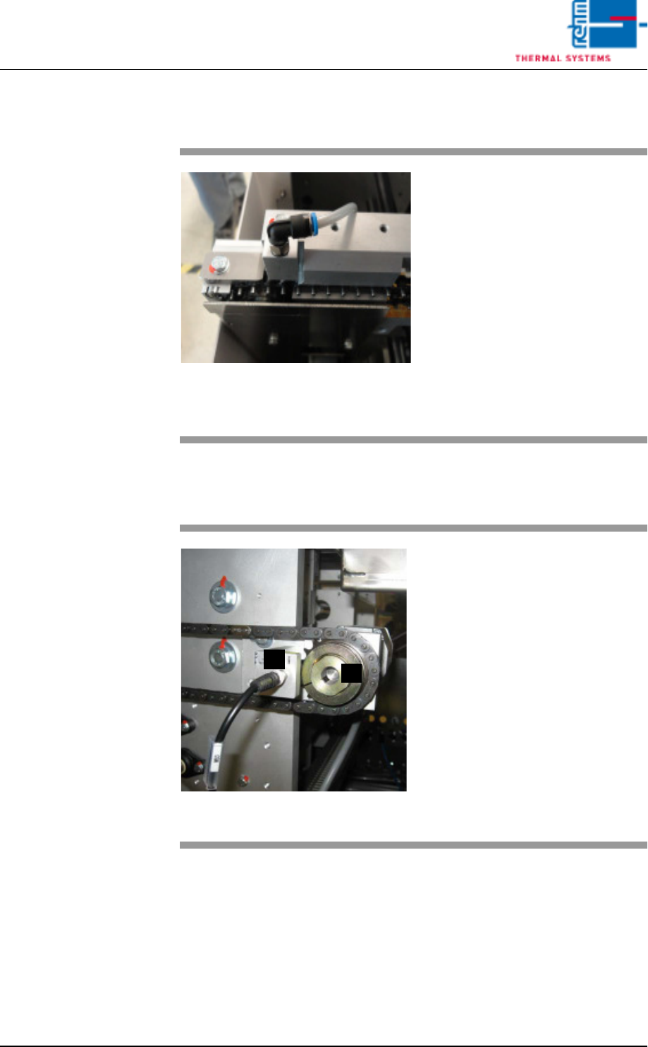
4.3.6 Fully automatic chain oiler VXP+
4.3.7 Conveyor Speed Monitoring
Fig. 4-15 Fully automatic chain oiler VXP+
The central lubrication unit dispens-
es high temperature lubricant to the
transport and plate link chains as
droplets. This drip feed chain oiler
needs no maintenance.
A belt pulse sensor runs whenever
transport is switched on. Lubrication
is triggered when the set belt pulses
occur.
If necessary, the customer can
change pulse times and duration
and store these via the chain oiler
screen.
Fig. 4-16 Conveyor Belt Pulse Sensor and
Slip Clutch
The actual speed of the conveyor
system is detected by the pulse sen-
sor at the chain sprocket, and is ac-
quired by the controller in order to
monitor conveyor speed.
Actual conveyor speed is compared
with the setpoint specified by the op-
erator. If the selected tolerances are
exceeded or fallen short of, optical
and acoustic alarm signals are gen-
erated.
A) Conveyor belt pulse sensor
B) Slip clutch
A
B
Vision XP+ VAC Page 53
4 Equipment
4.3 Conveyor System
Operating Instructions
Version 1.5
4.3.8 Inlet and Outlet Interfaces
4.3.9 CCS Retro-Reflective Sensor VXP/VXP+ (optional)
Fig. 4-17 Inlet / Outlet Interface
The peripheral devices at the sys-
tem’s inlet and outlet is integrated
via these interface.
Interfaces from various manufactur-
ers are utilized depending upon the
respective requirements. Smema
and Siemens interfaces are avail-
able as standard equipment.
Fig. 4-18 CCS Sensor
If Capability Control System (CCS)
is mounted, the inlet light barrier is
used as start signal for measuring
points.
The sensor must be cleaned at reg-
ular intervals.
The inlet sensor must not be mis-
aligned.
The sensor must be cleaned reg-
ular.
Page 54 Vision XP+ VAC
4 Equipment
4.3 Conveyor System
Operating Instructions
Version 1.5
4.3.10 Center Support
The center support prevents the PCBs from sagging as a result of exposure
to heat.
The position of the CS
1
is entered directly to the PC as a setpoint (see
Fig. 5-11 Main Window, on page 85.).
Safety limit switches prevent violation of minimum and maximum values.
If the CS is not needed, it can be advanced to the parking position. The park-
ing position is at the fixed side panel.
1. CS = Center Support
Fig. 4-19 CS Leaf Chain
The PCBs are supported by the leaf
chain which is guided via an alumi-
num profile rail during transport
through the system. The center sup-
port and the chain conveyor are op-
erated synchronously.
Lash chain is led back outside pro-
cess chamber, under the oven.
Fig. 4-20 CS Height Adjustment
Height is adjusted by means of a
gate.
The gate is located at the mechani-
cal stations. The absolute rotary en-
coder used for acquiring travel is
next to the motor at the oven outlet.