OperationInstruction_Vsision XP - 第62页
Page 54 Vision XP+ V AC 4 Equipment 4.3 Conveyor System Operating Instructions V ersion 1.5 4.3.10 Ce nter Support The center s upport prevents the PCBs from s agging as a result of e xposure to heat. The position of t h…
Vision XP+ VAC Page 53
4 Equipment
4.3 Conveyor System
Operating Instructions
Version 1.5
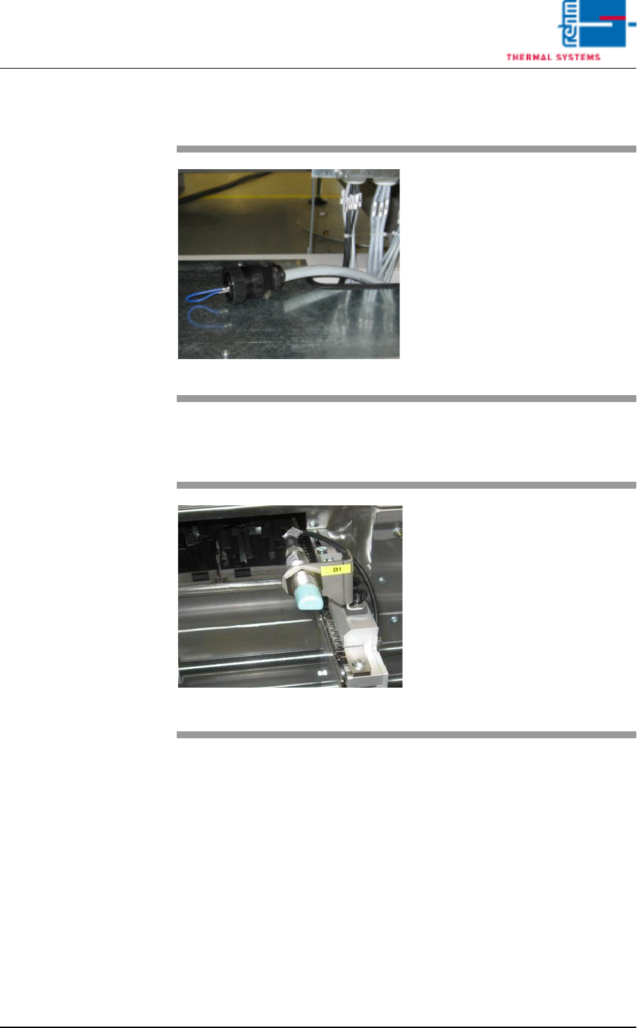
4.3.8 Inlet and Outlet Interfaces
4.3.9 CCS Retro-Reflective Sensor VXP/VXP+ (optional)
Fig. 4-17 Inlet / Outlet Interface
The peripheral devices at the sys-
tem’s inlet and outlet is integrated
via these interface.
Interfaces from various manufactur-
ers are utilized depending upon the
respective requirements. Smema
and Siemens interfaces are avail-
able as standard equipment.
Fig. 4-18 CCS Sensor
If Capability Control System (CCS)
is mounted, the inlet light barrier is
used as start signal for measuring
points.
The sensor must be cleaned at reg-
ular intervals.
The inlet sensor must not be mis-
aligned.
The sensor must be cleaned reg-
ular.
Page 54 Vision XP+ VAC
4 Equipment
4.3 Conveyor System
Operating Instructions
Version 1.5
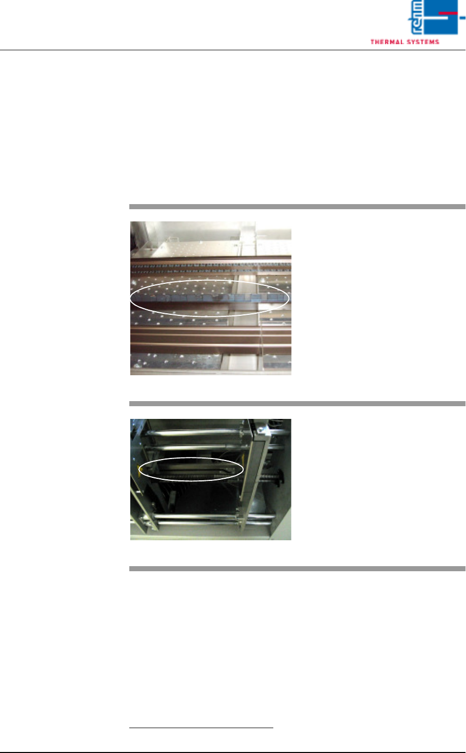
4.3.10 Center Support
The center support prevents the PCBs from sagging as a result of exposure
to heat.
The position of the CS
1
is entered directly to the PC as a setpoint (see
Fig. 5-11 Main Window, on page 85.).
Safety limit switches prevent violation of minimum and maximum values.
If the CS is not needed, it can be advanced to the parking position. The park-
ing position is at the fixed side panel.
1. CS = Center Support
Fig. 4-19 CS Leaf Chain
The PCBs are supported by the leaf
chain which is guided via an alumi-
num profile rail during transport
through the system. The center sup-
port and the chain conveyor are op-
erated synchronously.
Lash chain is led back outside pro-
cess chamber, under the oven.
Fig. 4-20 CS Height Adjustment
Height is adjusted by means of a
gate.
The gate is located at the mechani-
cal stations. The absolute rotary en-
coder used for acquiring travel is
next to the motor at the oven outlet.
Vision XP+ VAC Page 55
4 Equipment
4.4 The Process Chamber
Operating Instructions
Version 1.5
4.4 The Process Chamber
The process zone is subdivided into the following segments: inlet area,
calming region (nitrogen lock), heating chamber, cooling tract and outlet ta-
ble. The system’s modular design allows for flexible zone setups. This
means that the number of heating zones and the cooling tract can be better
adapted to the PCBs to be soldered.
Each individual segment can be opened manually for the performance of
maintenance work.
Please refer to the data sheet which is included in the documentation regard-
ing process chamber technical data. These data make reference to standard
system types, and may vary optionally depending upon provided system
equipment.
4.4.1 Opening/Closing the Process Chamber
The process chamber is opened and closed in a stepless fashion by means
of an electric motor. The entire process chamber cannot be opened manu-
ally.
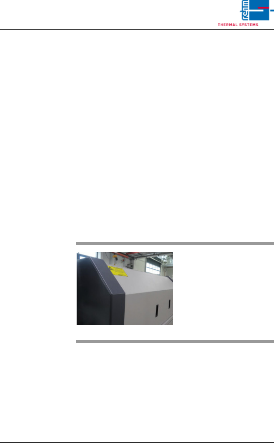
4.4.2 Removing the System Hood
Fig. 4-21 Removing the System Hood
The system hoods are removed
manually.
They are opened to this end with the
appropriate wrench and then lifted
out.