OperationInstruction_Vsision XP - 第66页
Page 58 Vision XP+ V AC 4 Equipment 4.4 The Process Chamber Operating Instructions V ersion 1.5 4.4.6 Heating Chamber Fig. 4-2 6 Prehea ting Preheating i s distributed ov er sever- al heating zon es which are locate d ab…
Vision XP+ VAC Page 57
4 Equipment
4.4 The Process Chamber
Operating Instructions
Version 1.5
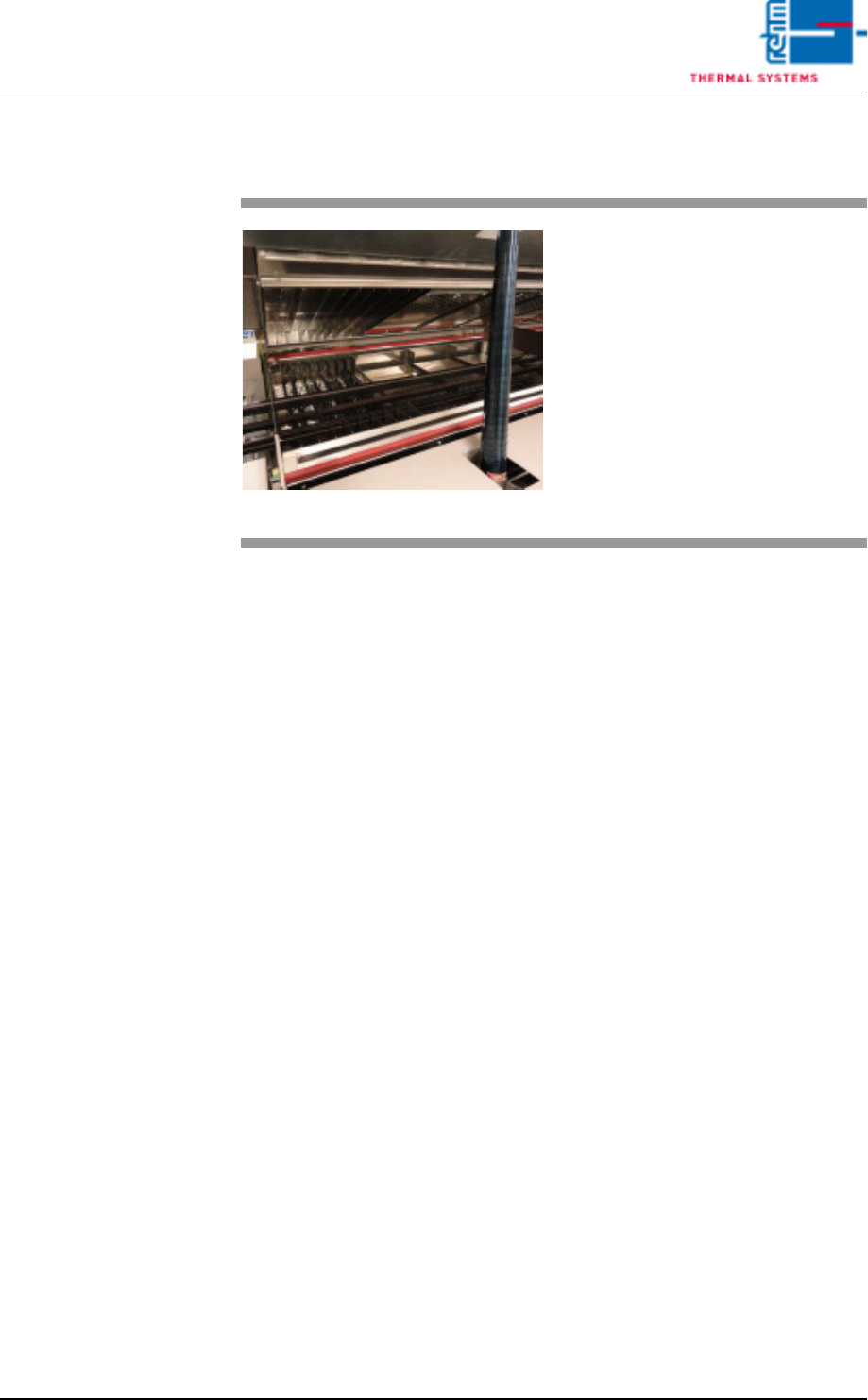
4.4.5 Nitrogen Lock at the Inlet
Fig. 4-25 Nitrogen Lock at the Inlet
The nitrogen lock functions as a
thermal barrier between the work
area at the inlet and the heating
chamber.
It is comprised of flow barriers, and
it improves the oxygen-free state of
the air.
Page 58 Vision XP+ VAC
4 Equipment
4.4 The Process Chamber
Operating Instructions
Version 1.5
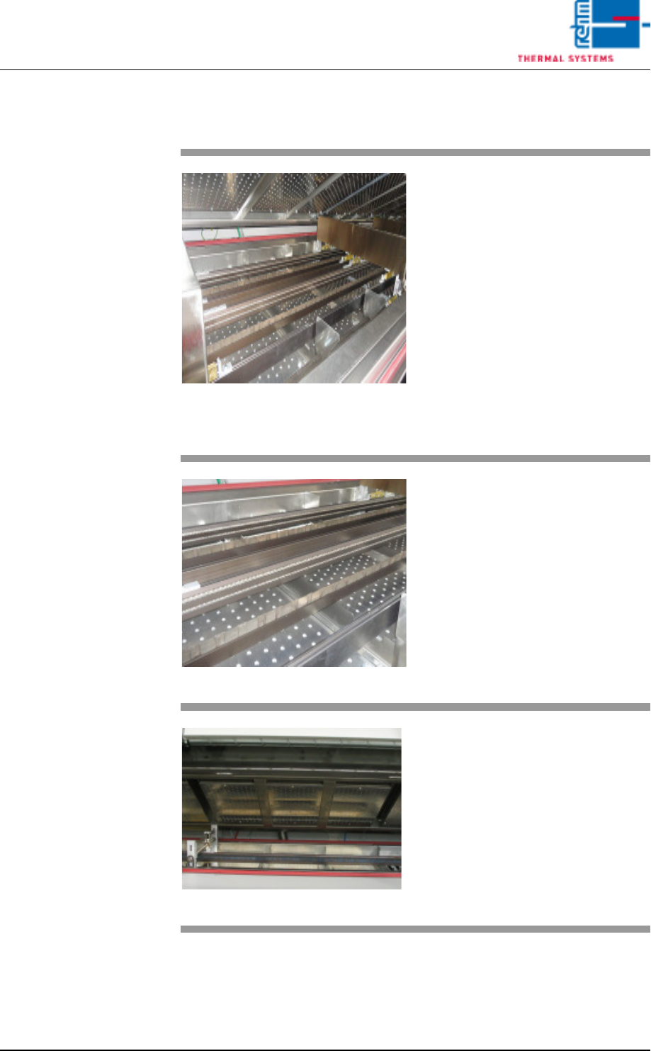
4.4.6 Heating Chamber
Fig. 4-26 Preheating
Preheating is distributed over sever-
al heating zones which are located
above and below the conveyor sys-
tem. The heating zones can be ad-
justed independent of each other.
The atmosphere in the individual
zones is circulated by means of
fans, heated up with tubular heaters
and returned to the process via noz-
zle sheets.
Temperature is regulated with the
help of temperature sensors which
are installed in direct proximity to
the tubular heaters.
Fig. 4-27 Preheating at the Bottom
Simultaneous heating of the PCBs
from above and below in the pre-
heating zone allows for the solder-
ing of PCBs with especially high
masses just as quickly as normal
PCBs.
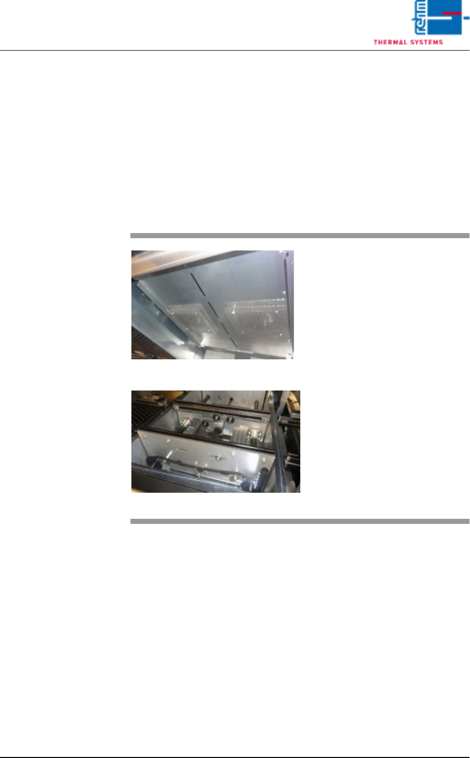
Fig. 4-28 Peak Zone
The peak zone (soldering zone) is
subdivided into heat zones which
are located above and below the
conveyor system. They can be ad-
justed independent of each other.
Due to the fact that more heating
power is required in the peak zone
than for preheating, tubular heaters
with greater heating power are in-
stalled here for the hot gas areas.
Vision XP+ VAC Page 59
4 Equipment
4.4 The Process Chamber
Operating Instructions
Version 1.5
4.4.7 Vacuum zone
The vacuum chamber is located between the peak zone and cooling zone.
The processing time for a vacuum is made up of the individual steps.
The steps are as follows:
The product enters the vacuum chamber, the chamber closes, a vacuum is
drawn, the vacuum is vented, the chamber opens, and the product is
removed from the chamber.
If the vacuum process is not intended for a product, the zone can be used
as a peak zone
Fig. 4-29 Vacuum chamber
Fig. 4-30 Vacuum chamber
The modules enter into the machine
and are detected by an input sen-
sor.