OperationInstruction_Vsision XP - 第67页
Vision XP+ V AC Page 59 4 Equipment 4.4 The Process Chamber Operating Instructions V ersion 1.5 4.4.7 V acuum zone The vacuum chamber is locate d between the peak zone and cooling zon e. The process ing time for a vacuu …
Page 58 Vision XP+ VAC
4 Equipment
4.4 The Process Chamber
Operating Instructions
Version 1.5
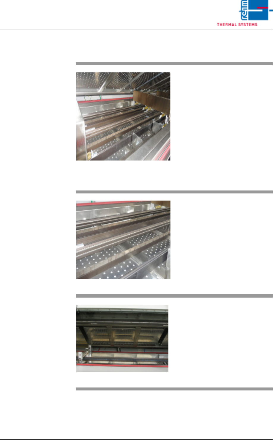
4.4.6 Heating Chamber
Fig. 4-26 Preheating
Preheating is distributed over sever-
al heating zones which are located
above and below the conveyor sys-
tem. The heating zones can be ad-
justed independent of each other.
The atmosphere in the individual
zones is circulated by means of
fans, heated up with tubular heaters
and returned to the process via noz-
zle sheets.
Temperature is regulated with the
help of temperature sensors which
are installed in direct proximity to
the tubular heaters.
Fig. 4-27 Preheating at the Bottom
Simultaneous heating of the PCBs
from above and below in the pre-
heating zone allows for the solder-
ing of PCBs with especially high
masses just as quickly as normal
PCBs.
Fig. 4-28 Peak Zone
The peak zone (soldering zone) is
subdivided into heat zones which
are located above and below the
conveyor system. They can be ad-
justed independent of each other.
Due to the fact that more heating
power is required in the peak zone
than for preheating, tubular heaters
with greater heating power are in-
stalled here for the hot gas areas.
Vision XP+ VAC Page 59
4 Equipment
4.4 The Process Chamber
Operating Instructions
Version 1.5
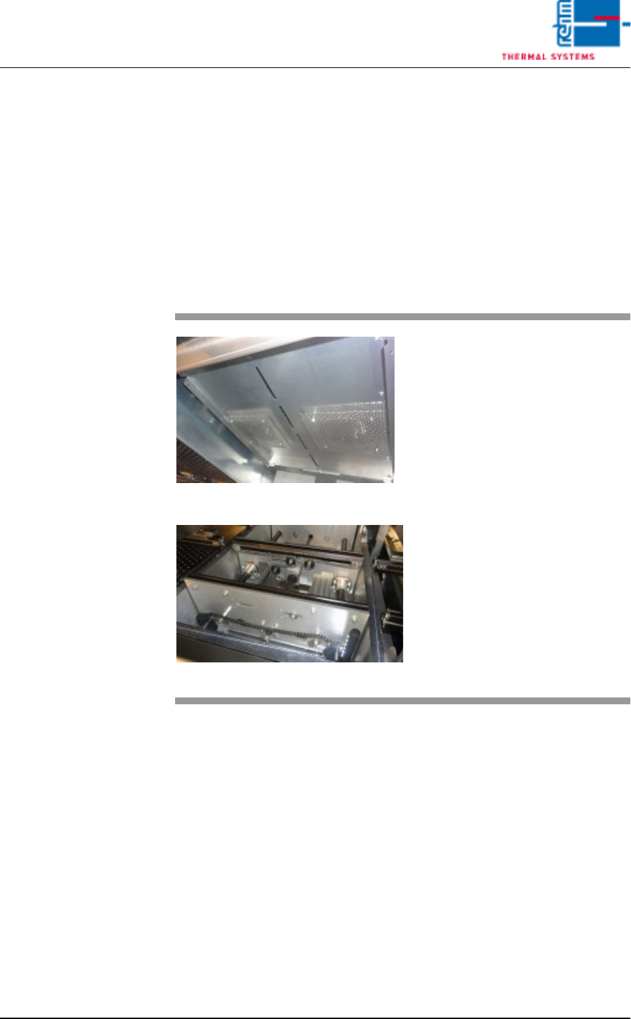
4.4.7 Vacuum zone
The vacuum chamber is located between the peak zone and cooling zone.
The processing time for a vacuum is made up of the individual steps.
The steps are as follows:
The product enters the vacuum chamber, the chamber closes, a vacuum is
drawn, the vacuum is vented, the chamber opens, and the product is
removed from the chamber.
If the vacuum process is not intended for a product, the zone can be used
as a peak zone
Fig. 4-29 Vacuum chamber
Fig. 4-30 Vacuum chamber
The modules enter into the machine
and are detected by an input sen-
sor.
Page 60 Vision XP+ VAC
4 Equipment
4.4 The Process Chamber
Operating Instructions
Version 1.5
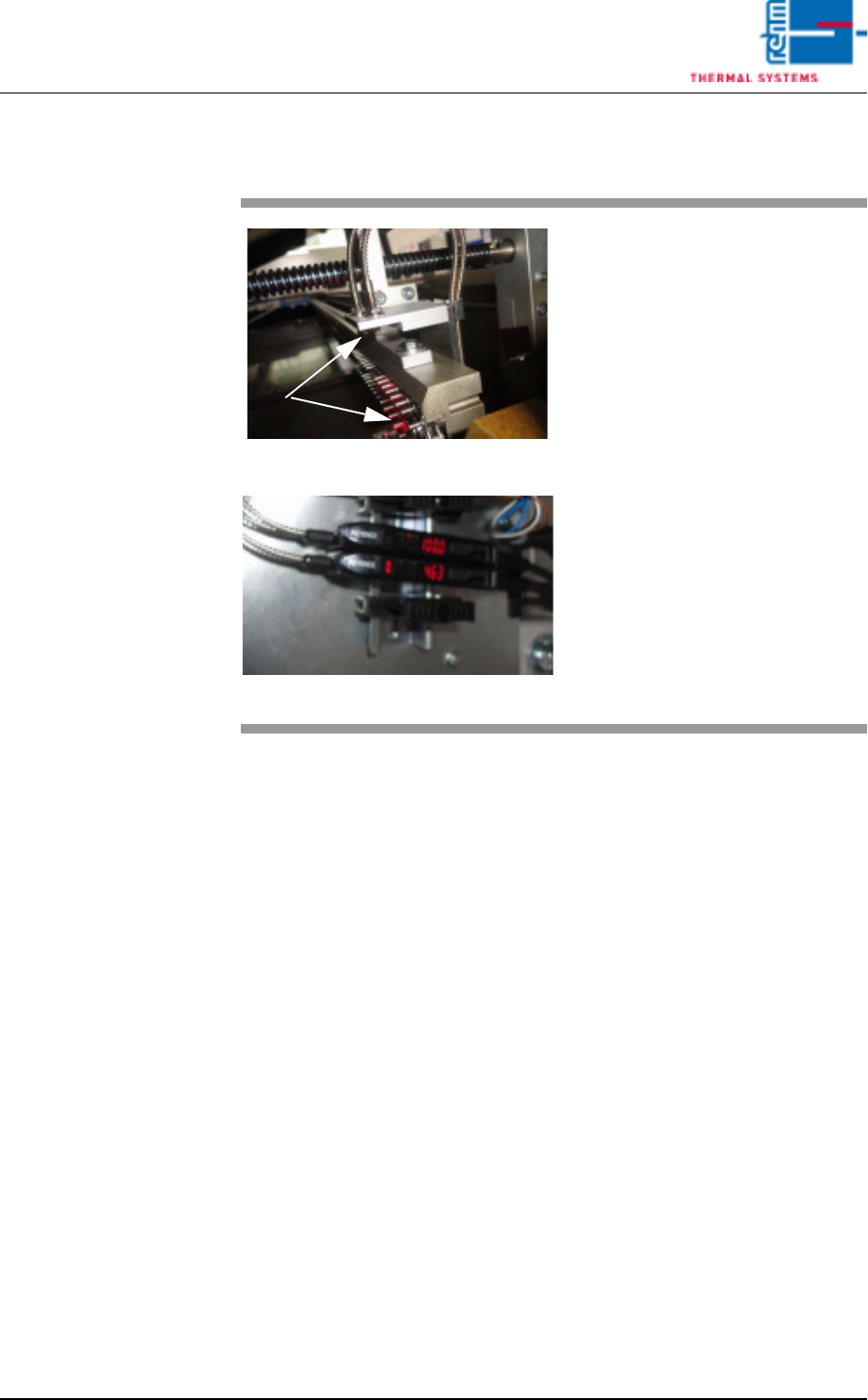
4.4.8 Sensors at the vacuum chamber
Fig. 4-31 Sensors at the Vacuum chamber
Fig. 4-32 Sensors at the Vacuum chamber
Optical fibre sensors are mounted
before and after the vacuum
chamber for PC board identification.
The sensors’ degree of soiling is
determined via the light intensity.
Cleaning and setting are described
in detail in the “Maintenance"
Chapter.