OperationInstruction_Vsision XP - 第82页
Page 74 Vision XP+ V AC 4 Equipment 4.10 Control Cabinets Operating Instructions V ersion 1.5 4.10 Control C abinets The control ca binets are located u nderneath the proces s chamber at the front of the sy stem. They ar…
Vision XP+ VAC Page 73
4 Equipment
4.9 Nitrogen (optional)
Operating Instructions
Version 1.5
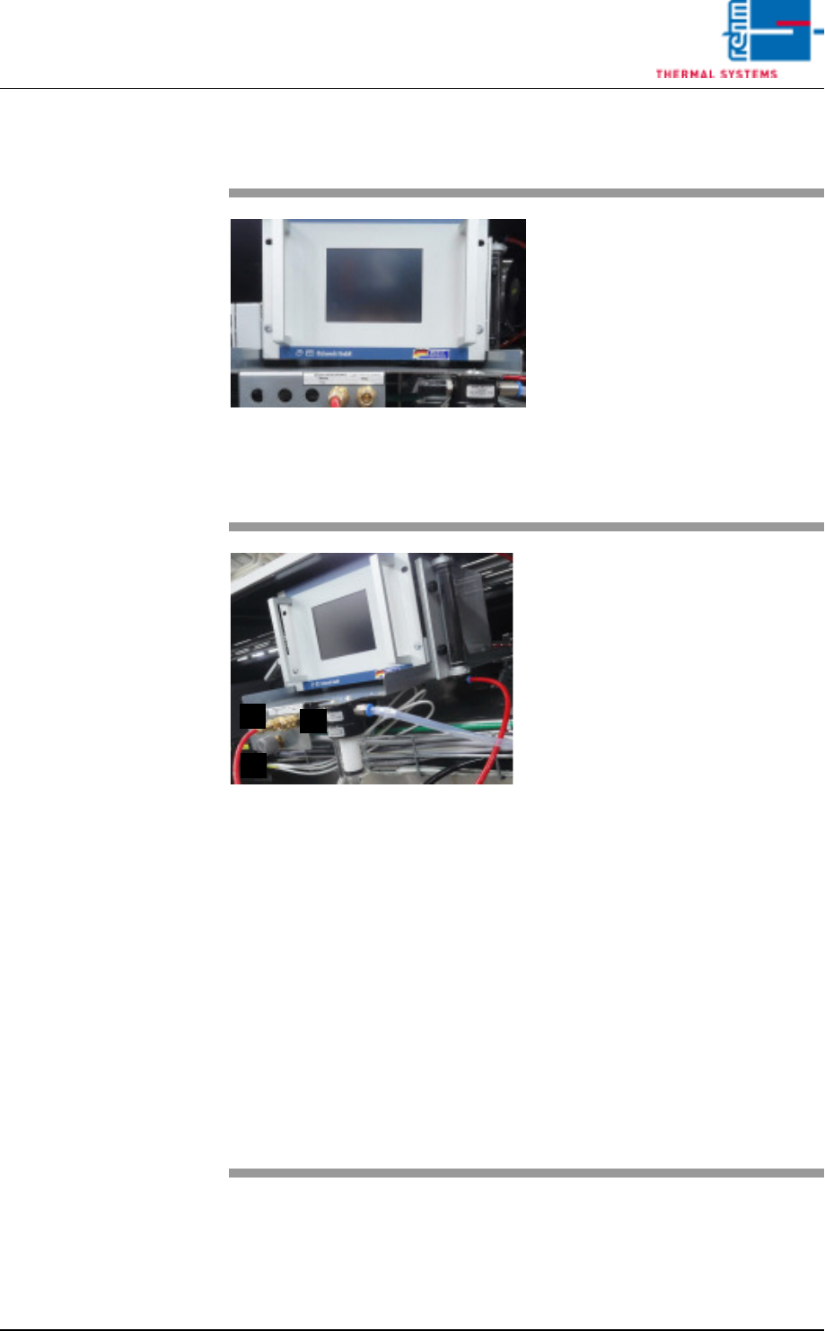
4.9.5 Residual Oxygen Measurement (optional)
Fig. 4-56 Residual Oxygen Measuring In-
strument
Residual oxygen content within the
system is checked in the event of:
– Initial start-up
– Process monitoring
– Deterioration of soldering results
– Relocation of the system
Residual oxygen measuring device
is required for measurement. Mea-
surement device as well as mea-
surement connections are located
at the system rear side.
Fig. 4-57 Residual Oxygen Measuring In-
strument: Connections
The measuring points mains (A) und
peak (B) are available as standard.
Optionally, the measuring points
can be extended to pre-heating,
centre and cooling section.
The quality of the nitrogen supply to
the system can be checked on the
basis of the measuring point net-
work.
Proceeding:
Open adjusting valve C by one turn
(nitrogen escapes at T – piece of the
measuring point mains).
Plug in the measurement connec-
tion at the mains.
Measured residual oxygen content
is displayed at the monitor screen,
as well as at the meter. A limit value
with alarm signal can be specified
by the user.
For detailed information regarding
use refer to the included Operating
Instructions for the Measuring In-
strument.
B
A
C
Page 74 Vision XP+ VAC
4 Equipment
4.10 Control Cabinets
Operating Instructions
Version 1.5
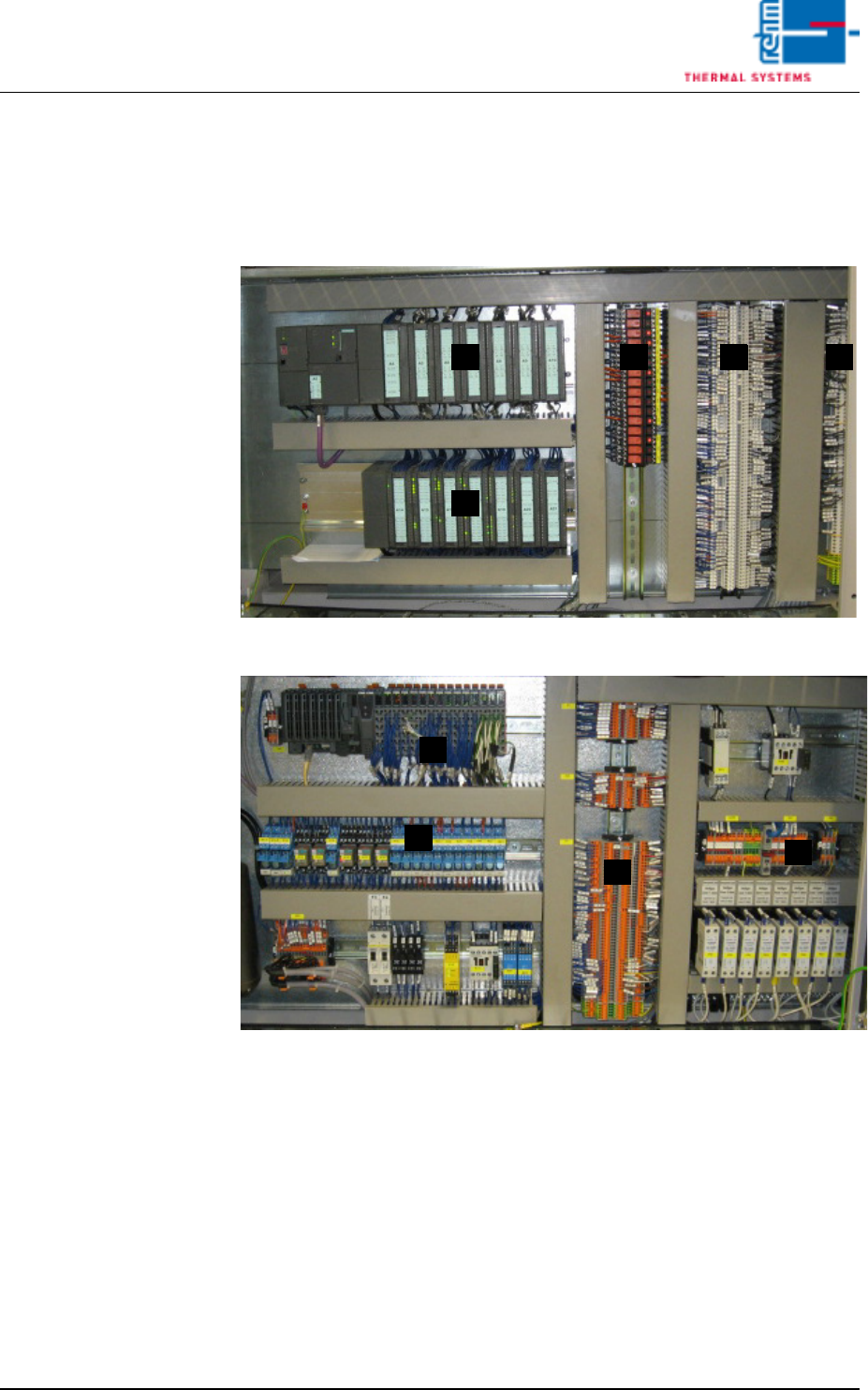
4.10 Control Cabinets
The control cabinets are located underneath the process chamber at the
front of the system. They are described beginning at the inlet.
Control Cabinet,
Section 1
Fig. 4-58 Control Cabinet, Section 1 (with Siemens-control)
Fig. 4-59 Control Cabinet, Section 1 (with B&R-control)
The controller and the distributor terminals are located in the first control
cabinet. Either a Bernecker & Reiner (B & R) controller, or optionally a Sie-
mens controller, is installed to the cabinet.
A) controller and modules
B) 24V-relay
C) X1-clamps
D) X-24V-clamps und Xminus-clamps
BA C D
A
A
B
C
D
Vision XP+ VAC Page 75
4 Equipment
4.10 Control Cabinets
Operating Instructions
Version 1.5
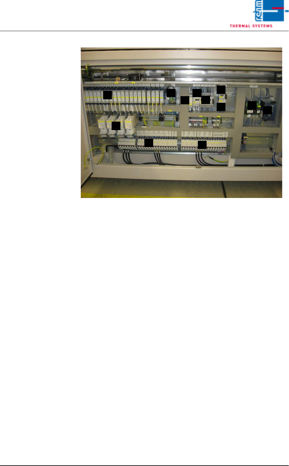
Control Cabinet,
Section 2
Fig. 4-60 Control Cabinet, Section 2
The second control cabinet houses the following components:
A) Solid-State relay
B) Current alarm module
C) Phase monitoring
D) Thermal Protector for motor
E) Lifting motor load relay (process chamber)
F) Water pump contactor
G) Thermal protector for the water pump
H) Power controller
I) Overcurrent monitoring
J) 24 V power pack
K) Fuse
C
B D
G
I
H
E
J
K
F
A
K