OperationInstruction_Vsision XP - 第92页
Page 84 V ISION XP+ V AC 5 Software 5.2 Main Window Operating Instructions V ersion 1.5 maintenance an d service work. If you do not possess the required au- thority for u nlocking t he condensate trap, the button appear…

VISION XP+ VAC Page 83
5 Software
5.2 Main Window
Operating Instructions
Version 1.5
fluences cooling efficiency. Coolant air volumetric flow can be regulated
with the frequency converter.
G) Pyrolysis display (optional))
The actual temperature of the pyrolysis is displayed here.
H) Temperature display for the heaters underneath the conveyor.
1
The desired tolerance can be selected with the Rel- and Rel+ parameters
in the Heating window.
I) Temperature setpoints for the heaters underneath the conveyor are en-
tered here directly.
1
The same values can be changed in the Heating
window.
J) Residual oxygen content display (optional).
If the display panel is blank, the analyzing unit is on display.
If the analyzing unit is (still) not ready, 999999 is displayed.
K) Cooling system intern water temperature display (only for systems with
external cooling).
1
L) Reset Emergency-Stop Button
The emergency-stop buttons snap into place when actuated. The “Reset
Emergency-Stop” button and the „Reset Alarm“ button must be activated
in order to reset the emergency stop circuit.
M) Operating Modes
The service mode is selected when maintenance, setup and repairs are
necessary. Safety devices used for monitoring whether or not the pro-
cess chambers are closed are disabled in this operating mode. Only ap-
propriate trained personnel may work with the system in the service
mode!
The automatic operating mode is used when the system is operated un-
der normal circumstances. The heating chamber and the cooling tract are
closed. The “open/close heat chamber”, “reset load” and “manual con-
veyor adjustment” functions are disabled for safety reasons.
N) Conveyor Adjustment
Switch is set to Auto: Conveyor adjustment is activated if a new setpoint
has been entered, if the setpoint deviates from the actual value and if
there are no PCBs in the system.
Switch is set to
Manual
: Conveyor adjustment is activated if the operating
mode selector switch is set to service if the scroll keys for conveyor
adjustment or the center support are activated.
In addition there are no PCB´s in the system.
If conveyor adjustment is switched from automatic to manual, the
conveyor adjustment comes to a standstill. Functioning is the same as
with manual operation. If conveyor adjustment is switched from manual to
automatic and all actual values are within the specified tolerances,
conveyor adjustment remains inactive until a new setpoint is entered.
However, if any of the actual values are not within the specified
tolerances, everything is repositioned.
O) Software button for condensate trap
The condensate trap is unlocked with this button in order to execute
1. See also page 80, “Use of Color” and “Entering Values”.
Page 84 VISION XP+ VAC
5 Software
5.2 Main Window
Operating Instructions
Version 1.5
maintenance and service work. If you do not possess the required au-
thority for unlocking the condensate trap, the button appears gray and is
disabled.
Indication Condensation Trap unlocked or locked
There is a display on the right side of the switch.
Condensation Trap open = orange.
Condensation Trap closed: = light green.
Indication of fans in the Condensation Trap:
- Init = Fans of Condensation Trap are initialized.
- Stop = Fans of Condensation Trap are stopped.
- Standstill = Fans of Condensation Trap come to a standstill.
- Start = Fans of the Condensation Trap are started.
- Run = Fans of Condensation Trap are running.
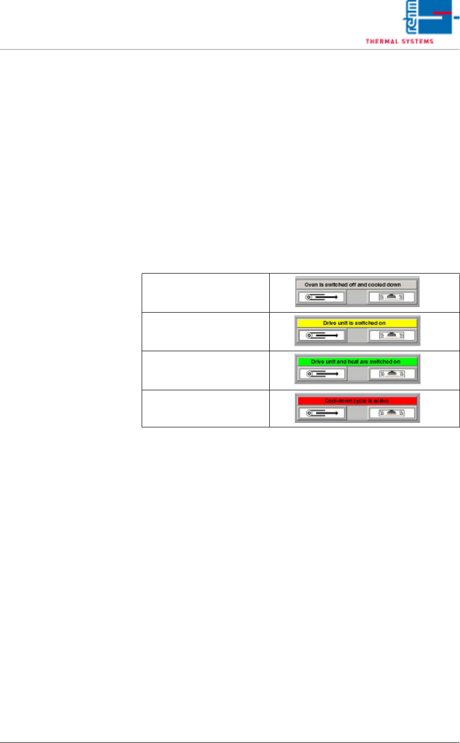
P) System status is displayed here. There are four different statuses::
Q) Alarm Button
The Alarm window appears (see chapter 5.5.1, “Alarms”, on page
105).Green if no alarm is available.
Orange if no alarm is available which is to be acknowledged (or was al-
ready acknowledged)
Red if an alarm is available which is to be acknowledged.
R) Horn Button
Confirm the horn. This will disable the horn for about 2 minutes.
S) Nitrogen Mode (optional)
On: Soldering is executed in a nitrogen atmosphere, servo-valves are
open. Off: Soldering is executed in air, servo-valves are closed in a time
delayed fashion.
System is switched off and
cooled down (use of color:
grey)
Drive unit is switched on
(use of color: yellow)
Drive unit and heat are
switched on (use of color:
green)
Cool-down cycle is active
(use of color: red)
VISION XP+ VAC Page 85
5 Software
5.2 Main Window
Operating Instructions
Version 1.5
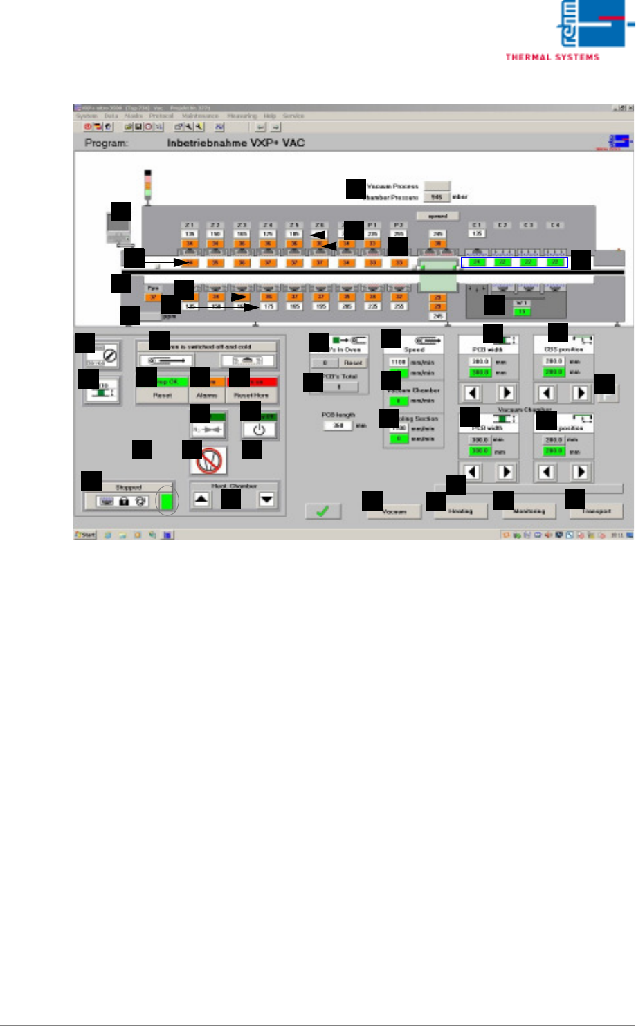
Fig. 5-11 Main Window
T) Standby mode
The standby mode is an energy saving mode. It’s activated as soon as
the system is empty, assuming there are no pending requests for new
PCBs.
An on-time count-down is initialized when the standby mode is activated.
After the specified time has elapsed, fan frequency is reduced.
If the standby mode is active and a request occurs for a new PCB, an off-
time count-down is started. After the specified time has elapsed, fan fre-
quency is restored to it original value.
The standby mode can be manually started or ended with the standby
button. The text displayed above the button indicates the current status
of the standby mode. The following statuses are possible:
- Standby off: The standby mode is deactivated.
- Empty conveyor: The conveyor is run until it is empty.
- Start-up count-down: Power-up delay time is running.
- Standby on: The standby mode is active.
- Stop count-down: Shutdown delay time is running.
U) Pin-in-Paste
Is the function active and the temperature in the first zone under 160 °C
t, the heating and the blower are switched off in the first bottom zone. The
supervision of the motor in this zone is no longer active. With program
change from „Pin in Paste“ to normal or from „Pin in Paste“ to „Pin in
Paste“ the transport adjustment is locked. The transport adjustment is
locked as long as the function is active. With program change the trans-
F
E
G
H
B
A
C
D
I
J
Q
AA
Z
Y
X
W
V
U
T
S
R
P
O
N
M
L
K
AL
AH
AB
AF
AG
AJ
AI
AC
AD
AE
AM
AK