OperationInstruction_Vsision XP - 第98页
Page 90 V ISION XP+ V AC 5 Software 5.3 The Menu System Operating Instructions V ersion 1.5 5.3 The Menu System 5.3.1 Password Entry Fig. 5-1 9 Passw ord Entr y The respective employee can log o n to the system’s user in…
VISION XP+ VAC Page 89
5 Software
5.2 Main Window
Operating Instructions
Version 1.5
Further Possible
Functions (optional)
Fig. 5-13 C
mk
Value
The Capability Control System program
(CCS) is launched in the background as
a client/server when Visu2 is started. It
archives all relevant data from the C
mk
calculation. The C
mk
value is calculated
for each zone, and the smallest value is
transferred to Visu2 as a variable.
Fig. 5-14 Enable Interface at Inlet
If no enabling signal is transmitted to the
upstream module by the interface at the
inlet, no PCBs can be advanced into the
system. The interface can nevertheless
be enabled with this button.
Fig. 5-15 Disable Interface at Inlet
If an enabling signal is transmitted to the
upstream module by the interface at the
inlet, PCBs can be advanced into the
system assuming it is ready for opera-
tion. The enabling signal is suppressed
when this button is activated. This button
takes precedence over the “Enable Inter-
face” button.
Fig. 5-16 Product/Program
Changeover
This display becomes active when a pro-
gram changeover is supposed to take
place, but the system is loaded.
Fig. 5-17 Buffer Conveyor Empty
„Buffer transport empty“ / „Buffer outlet
stopped or full“ (Fifo)
Fig. 5-18 BSR-Back Side Reflow
BSR Back Side Reflow / undercooling –
Specific heating zones are cooled. This
is switched on /off by the button.
Page 90 VISION XP+ VAC
5 Software
5.3 The Menu System
Operating Instructions
Version 1.5
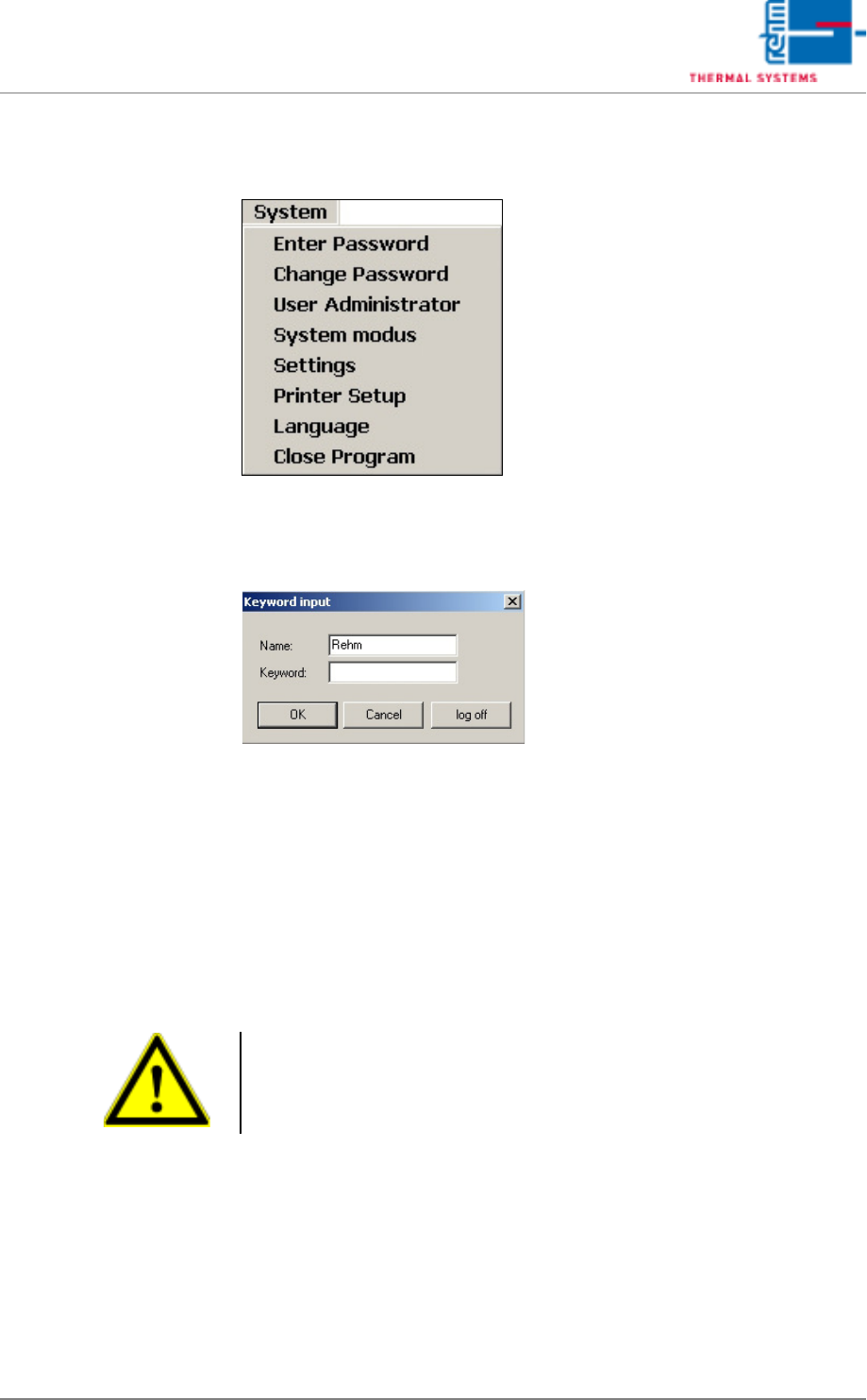
5.3 The Menu System
5.3.1 Password Entry
Fig. 5-19 Password Entry
The respective employee can log on to the system’s user interface by filling
in the Name and Password fields, and acknowledging his entry with the OK
button.
The operator can log back off by clicking the Logoff button. The user inter-
face is then disabled.
No more work can be carried out until a valid Name and Password are once
again entered.
Note!
Correct notation, including upper and lower case letters, must be adhered
to when entering Name and Password.

VISION XP+ VAC Page 91
5 Software
5.3 The Menu System
Operating Instructions
Version 1.5
5.3.2 Changing a Password
Fig. 5-20 Changing a Password
The currently logged on operator can enter a new password or change an
existing password in this window. Passwords may not exceed a length of 20
characters. Special characters may be used if desired.
If the operator forgets his password, the administrator can delete it as de-
scribed in the chapter entitled, “Resetting a Password”, on page 94.
After a new user is added, he must enter a password in this window the first
time the system is used.